4
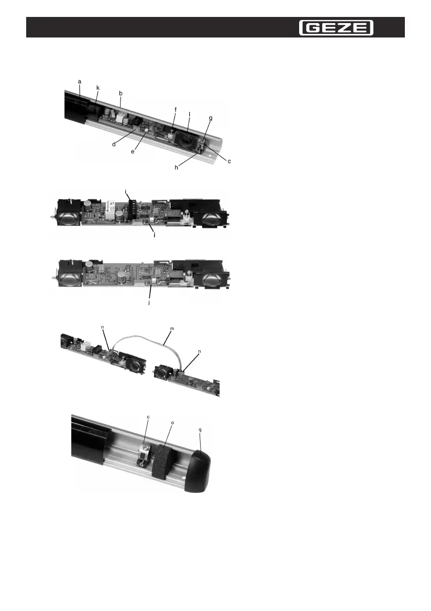
1 Design of the device
Figure 1.1 Internal design of the device
Figure 1.2 Design of the master module
Figure 1.3 Design of the slave module
Figure 1.4 Connection of two modules
Figure 1.5 Installation of the module holder and of the profile seal
a
Removable housing cover
b
Aluminum section
c
Module holder
d
Handle to set the angle of inclination
(chassis lever)
e
Function display for detection
f
Screw for mechanical setting of the
detection range
g
Screw to secure the angle of inclina-
tion
h
Headless screw to secure the module
holder
i
Terminal block for supply voltage, out-
put and test input
j
Configuration bridge
k
Infrared transmitter
l
Infrared receiver
m
Flat cable
n
Module connector
o
Profile seal
q
End caps
 Loading...