6
3.1.2 Installation of the Module
1. Set the transmitters of the modules identically at all modules to be used (cf. Figure 3.3). -> For
this purpose, push the transmitter adjustment always in direction of the flat conductor cable
(the flat conductor cable side is opposite the closing edge).
2. Connect all required flat conductor cables to the modules prior to the installation of the modules.
3. Please make sure that the master module is always located on the hinge plate side.
4. Connect the terminal screw (i) of the master module to the transition cable of the door control.
5. Place the modules between the module holders (c). Subsequently use the screw M2.5 (h) to
screw down to the module holder (cf.
Figure 1.1).
6. Use nippers to cut the configuration bridge (j) out of the PCB of the last module (last slave module
or individual master module) (cf.
Chapter 5).
7. Set the angle of inclination and the detection range in keeping with Chapter 3.2.
8. Place the housing orifice (a).
9. Subsequently screw down the end caps.
10. Finally, check the detection range for each beam.
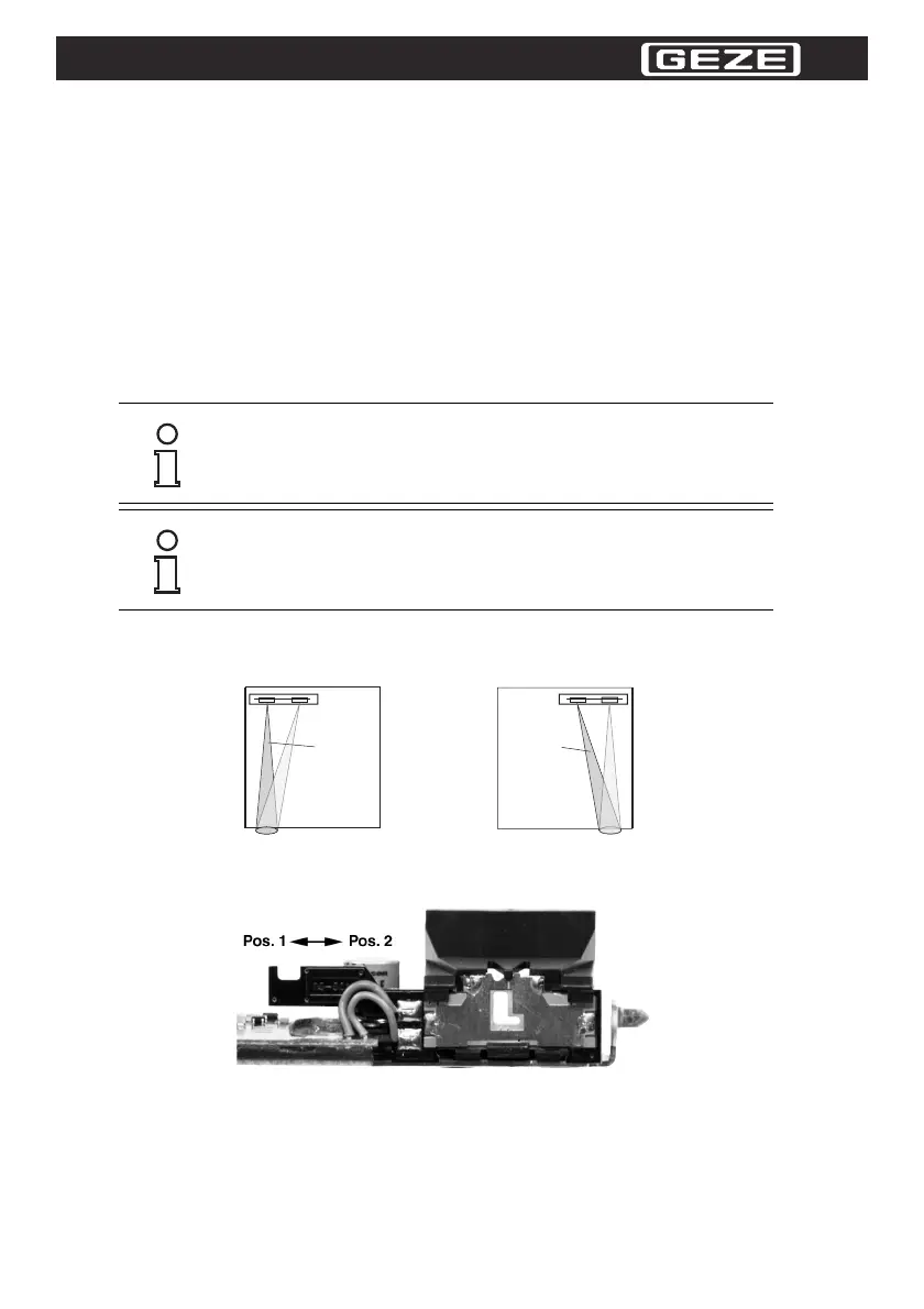
3.2 Setting the monitoring Beam - closing Edge
Set the transmitting or receiving beam upright in order to secure the closing edge as best as possible.
Figure 3.2 Explanation of the monitoring beam setting at the closing edge
Use two lock position to set a monitoring edge flush on the left or right side of the transmitter (cf. Figure
3.3.).
Figure 3.3 Setting the monitoring beam to the closing edge
In the factory default setting, all transmitter modules are preset to position 1 and the sensing range to
maximum. Position 1 means that the transmitter is straight and the closing edge is on the left (cf.
Figure
3.2 left).
Make sure that the transmitters are all set identical in case of several slave modules (identical lock po-
sition of the transmitter) ! The master module has to have the same transmitter setting as well.
The transition cable to the door control can be passed through the end cap by
means of a cable bushing.
If you use the accessories "GC 335 Ergänzungskit IP54", please fix a double-faced
scotch tape between the profile and the mounting surface. This avoids the intrusion
of water through the drills of the sensor profile.
Position 1
Position 2
 Loading...