9
5 Master / Slave Operation
5.1 Difference between Master and Slave Module
It is possible to fit up to seven additional slave modules, apart from one master module.
The differences between the master module and the slave module are as follows:
Master module: with relay; 6-pole connector; one red socket
Slave module: no relay; no 6-pole connector; two red sockets
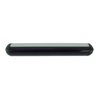
5.2 Installing Master / Slave Module
Make sure that the chassis neatly locks into the module holder during the installation of the master
module and the slave module.
Figure 5.1 Master / slave module
The chassis plate has to lock into the module holder as follows:
Figure 5.2 Installing master / slave module
• Please make sure that the arbor of the module holder locks into the borehole of the chassis safely.
The chassis clip has to be visible in the middle of the module holder (
Figure 5.2 Circle).
• Connect the master module only by means of the 6-pole terminal (i) to the door control.
• Connect the master module with the 24 cm flat cables provided for the purpose.
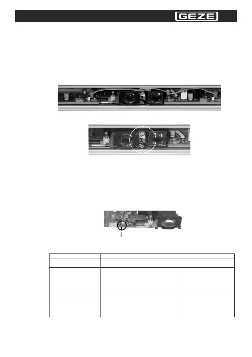
5.3 Removing the Configuration Bridge
Disconnect the configuration bridge (j) at the last slave module or on the last slave module's PCB or on
the master module's PCB.
Disconnect the bridge when the sensor is not powered.
Before carrying out this step, touch the chassis lever.
Figure 5.3 Configuration bridge
6 Fault analysis
Table 6.1 Fault analysis
Error Cause Remedy
The sensor does not initial-
ize or react.
Supply voltage is not correct. Check the voltage supply.
The door opens and closes
cyclically.
• The sensor is disturbed by the move-
ment of the door.
• The door leafs are detected by the sen-
sor.
• The door movement causes vibrations.
• Change the adjustment an-
gle.
• Check the attachment of the
sensor.
The door opens and closes
sporadically.
• There are objects in the detection field
which move in the air current.
• Remove the objects.
Test unit is not recognized.
• The detection range has been wrongly
set.
• The angle of inclination has been
wrongly set.
• Check the detection range
and the test card.
• Readjust the angle of incli-
nation (cf. Chapter 3.3).
 Loading...