5
2 Description of Function
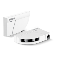
The GC 335 is an active infrared triangulation scanner.
The GC 335 has been designed for detection traveling on the door leaf.
2.1 Principle of Operation
Any objects entering the protected area will be detected by the infrared beams and will cause the relay
outputs to be switched off.
The beam spot produced by the infrared beam on the ground is approx. 1,1 cm x 8,3 cm in size (at a
mounting height of approx. 2
m).
The angle of the two lens systems can be modified by an adjustment mechanism. A detection range
(detection height of objects) of up to a maximum of 2.50
m can be set. The sensing range of the device
is set to maximum at the factory. The device has been fitted with an optical adjusting tool.
The sensor reacts to objects in the detection range largely independently of the surface color and struc-
ture. Reflecting and very dark objects are detected as well.
Several sensors can be operated in a master and slave combination in order to be able to adapt the
area protected to the prevailing conditions.
By means of a six-pole screw terminal the master module is connected to the door control. The slave
modules are connected to and supplied by the master module by means of flat cables. The master
module and the slave modules are located in an aluminum profile together.
3 Installation and initial Operation
3.1 Installation Check List
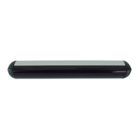
3.1.1 Installation of Aluminum Section
1. Push the module holder (c) into the aluminum profile (b) and position the module holder at the
points where the modules will be mounted later.
2. Drill the fastening holes in the middle between the module holders (in Fig. 3.1 grayed surface).
Make sure that no chips remain in the aluminum section.
Seal the borehole when fastening in such a way that no dripping water can penetrate.
Mechanical information which may facilitate the positioning of screws:
Figure 3.1 Mounting the aluminum section
3. Only use screws with a flat head to fasten the aluminum section, and mount the aluminum section
(b) at the intended mounting height (maximum 2.50
m).
The intended use of GC 335 is to secure automatic swinging door in keeping with
German standard DIN
18650 / EN 16005. If used as intended, the sensor shall influ-
ence the door movement through the safe door control only and not by direct inter-
vention as only the entirety of safe door control and sensor constitute a protective
device of Category 2 EN 954/1.
The modification of the construction/ arrangement of the installation without consul-
tation with the manufacturer could lead to dangerous situations.
GC335 GC335GC335 GC335GC335
0 mm 100 mm 290 mm 480 mm 670 mm 860 mm
100 mm 190 mm 190 mm 190 mm 190 mm
 Loading...