7
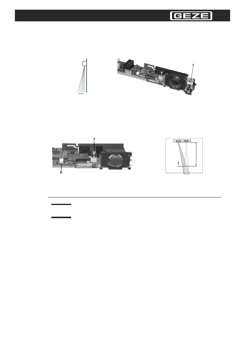
3.3 Optical Setting of the Sensor
You can swivel the detection field away from the door or towards the door by setting the angle of incli-
nation. The angle of inclination can be varied continuously from 0° to + 25°.
Use the handle on the chassis metal to set the angle of inclination.
For the adjustment of the angle of inclination use the M3 screw (g) at the top of the module holder.
Figure 3.4 Setting the angle of inclination
Use the detection range screw (f) to adjust the detection range.
By turning the detection range screw (f) with a screwdriver and the displacement of the receiver lens
caused, the detection range can be set.
An optical adjustment tool (LED green / red (p)) facilitates the exact adjustment of the detection range
over the ground.
If the sensor is not used for protection in keeping with German standard DIN 18650 /
EN
16005, a higher adjustment (no more than 80 cm) is possible.
Figure 3.5 Adjustment of the detection range
LED display:
LED red: Lens has been detected.
LED green: Free protected area and the sensor sees the ground.
Use the optional calibration tool (test card and square) for adjustment.
Detection range adjustment of the Sensor:
1. Use the chassis lever to set the module to the first marking line on the module holder (cf.
Illustration 6.3), and use the M3 screw to fasten (g).
2. Turn the detection range screw (f) counterclockwise until the overturn protection is activated
(slight "clicking" noise). Now the maximum detection range has been set.
3. Now use the test card and place it on the test specimen in such a way that it lays 12,5 cm above
the ground.
4. Turn the detection range screw clockwise until the LED display just switches from red to green (if
necessary turn back to red and then clockwise to just into green).
The detection range adjustment is thus completed.
If used as a means of protection in keeping with German standard DIN 18650 /
EN
16005, the angle of inclination and the detection range have to be adjusted as
follows:
 Loading...