EasyManua.ls Logo

GEZE Powerturn F User Manual

GEZE Powerturn F
98 pages
To Next Page IconTo Next Page
Page #1 background imageLoading...
Page #1 background image
Powerturn
Valid for variants:
Powerturn (1-leaf/2-leaf)
Powerturn F (1-leaf)
Powerturn F-IS (2-leaf)
Powerturn F/R (1-leaf)
Powerturn F/R-IS (2-leaf)
Powerturn F/R-IS/TS
EN Wiring diagram
156568-03

Table of Contents

Other manuals for GEZE Powerturn F

Question and Answer IconNeed help?

Do you have a question about the GEZE Powerturn F and is the answer not in the manual?

GEZE Powerturn F Specifications

General IconGeneral
Power supply230 V AC, 50/60 Hz
Safety featuresObstacle detection
Closing speedAdjustable
Opening speedAdjustable
Hold-open timeAdjustable
Ambient temperature+50°C

Summary

Powerturn Wiring Diagram

Notes and Safety Instructions

Important Safety Instructions

Crucial safety guidelines for installation and operation to prevent injury or damage.

Safety-Conscious Working Practices

Essential safety measures to prevent injuries during maintenance and operation.

Safety Sensors for Door Monitoring

Safety Sensor Open and Close Configuration

Configuration for safety sensors monitoring door opening and closing actions.

Push & Go and Configurable Inputs

Configurable Inputs Overview

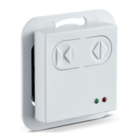
How to configure various inputs for special functions and operations.

Configurable Inputs - Specific Functions

Configurable Inputs - Advanced Operations

Configurable Inputs - Special Functions

STOP and Closed Position Inputs

Connecting stop push buttons and closed position detection inputs.

Configurable Outputs PA1 and PA2

PA1 Output Functions (Gong, Fault, Electric Strike)

Configuration and functions of PA1 for gong, fault, and electric strike signals.

PA1 Output - Advanced Functions

Configurable Output PA2 Functions

PA2 Gong, Faults, Electric Strike, Warning

Configuring PA2 for gong, faults, electric strikes, and warning signals.

PA2 Output - Advanced Functions

Electric Strike Systems

24V DC and 12V AC Electric Strikes

Details on 24V DC and 12V AC electric strikes and connections.

Electric Strike and Bolt Message Configuration

Bolt Message and Lock Switch Delay

Configuring bolt message functionality and lock switch activation delays.

WC Control and Mode of Operation

WC Control Functionality

Configuration and operation of the WC control function.

Mode of Operation Overview and Settings

Overview of operating modes and settings via mechanical switches.

Changing Operating Modes

2-Leaf Drive Systems

2-Leaf Drive System Overview

Specific considerations for 2-leaf drive systems.

Smoke Switch Control Unit Integration

Hold-Open System Configuration

Configuration for hold-open systems with specific leaf types and magnets.

Mains Connection Procedures

Motor Unit and Control Unit

Motor Details, Safety, and Control Unit Overview

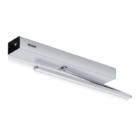
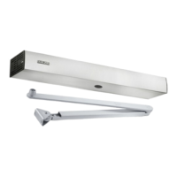
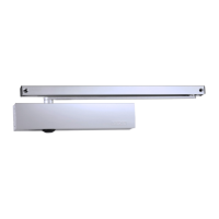
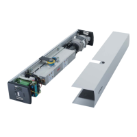
Information on the motor, safety, and the control unit components.

Commissioning and Service Procedures

Commissioning Steps, Requirements, and Teaching

Prerequisites, steps for commissioning, and drive teaching procedures.

Commissioning - Specific Systems

1-Leaf/2-Leaf Teaching and Parameter Adjustment

Teaching procedures for 1-leaf/2-leaf systems and adjusting forces/speeds.

De-energised Mode and Free Swing

Door Closer and Low-Energy Modes

Servo Mode Operation

Service Menu Access and Navigation

ST220 Service Menu - Parameter Configuration

ST220 Service Menu - Signals and Inputs

ST220 Service Menu - Diagnosis and Reset

ST220 Service Menu - Settings Management

Display Programme Switch (DPS) Operation

DPS Parameter Settings - Menu Details

DPS Parameter Settings - Inputs and Outputs

Fault Message Troubleshooting

Fault Message Details - Continued

Fault Messages on Service Button LEDs

Related product manuals