Staircase control unit THZ
38
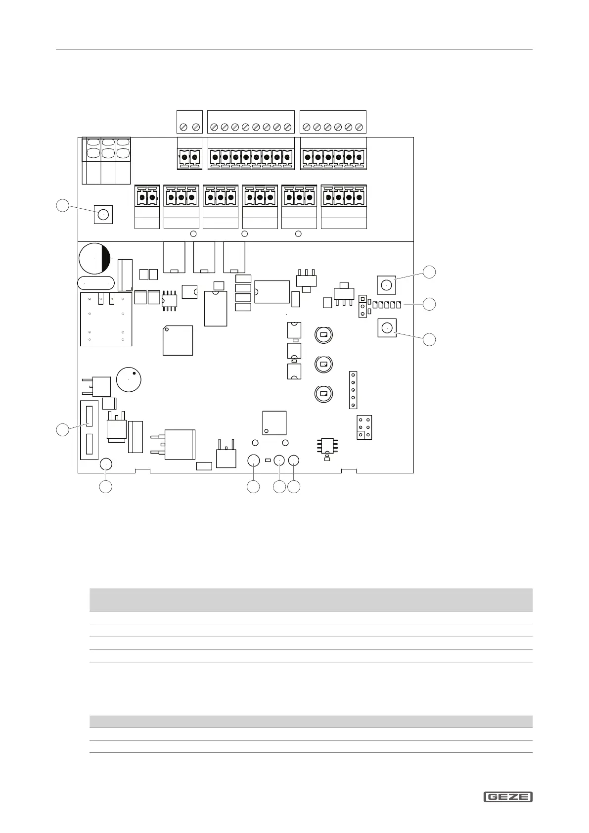
Connecting the THZ control unit
5.3 Connecting external components
5.3.1 Connection overview
X8 Motor
X3 Smoke detector
X4 RWA switch
X5 Vent switch
X2 BMZ
X9 PA1
X10 PA2
X11 PA3
X1 R/W
X6 PE1/2 (unused)
1 Service button
2 Service display
3 Battery –
4 Power pack –
5 Power pack +
6 Battery +
7 Fuse battery F1
8 Reset smoke detector switch
Cable cross-section
Connection Current Cable cross-sec-
tion/diameter
Cable
length
Terminal cross-
section (max.)
Miscellaneous
X4, X5
≤
100 mA ≥0.8 mm ≤400 m
1.5 mm
2
X2, X3
≤
100 mA ≥0.8 mm ≤400 m
1.5 mm
2
Max. of 10 smoke or heat detectors
X6
≤
200 mA ≥0.8 mm ≤400 m
1.5 mm
2
X9, X10, X11
≤
500 mA ≥0.8 mm ≤400 m
1.5 mm
2
Potential-free, max. 30 V
Calculation equation for cable cross-section (drives), X8
Cable cross-section = Cable length × Total current of all the drives / 73
Examples of maximum cable lengths depending on cable cross-section and total current of the drives:
Cable cross-section 1 A 2 A 4 A
1.5 mm
2
100 m 50 m 25 m
2.5 mm
2
180 m 90 m 45 m
Max. terminal cross-section: 2.5 mm
2