Staircase control unit THZ
41
Connecting the THZ control unit
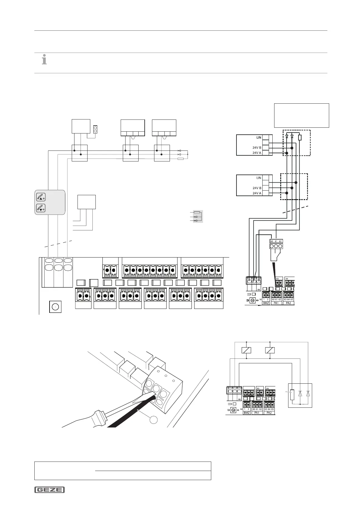
5.3.5 Connecting the drives
à Drives 24 V DC, max. 3.4 A
Connection of standard drive or IQ windowdrives without distinction
between ventilation and RWA operation
123
K
K
K K K K
K
K
K
K
K
K
X5
X6
V83V81
X1
V38V84
X11X10
V86
X3
V5
X9
X2
V22
S9
V82V25V85
X4
V87
V68
X8
Resistor 2k2
1st motor 2nd motor Last motorIsolate
Conductor 3
Branching box
Alternative connection possibilities:
Connection of motors with integrated
line monitoring
Last motor
3× ... mm
2
(calculate cable
cross-section)
321
bridge bridge
ABSL
Motor
24 V DC
IQ window
drive
Motor
24 V DC
– + =
+ –=
321
2x Diode 1N4007
ABSL
IQ window
drive
*) Alternatively: Use GEZE Cable end module LEM,
ID.no. 166090
3 WH
2 BK
1 BK
*)
Connection of IQ windowdrives
with distinction between
ventilation and RWA operation
Signal
Signal
Last drive
4×... mm
2
(calculate cable
cross-section)
1st drive
12
+24 V
Function relay alarm:
If alarm is triggered,
+24 V DC is applied
to the "Signal" line
3
2 diodes, 1N4007 in last
branching box for line
monitoring
IQ windowdrive
IQ windowdrive
*)
Relay PA1 has to be congured to
alarm
Removing the conductor at the motor terminal
X
Use a screwdriver to press on the terminal as shown in the gure
below and release the conductor (1).
Calculating cross-sections for motor cables
Min. cable cross-section 1.5 mm
2
Cable cross-section =
Cable length × Total current of all the drives
73
Connecting retention magnets or
electro-magnetic lock (max. 0.8 A)
Parameter “Motor operating mode” has to
be set to retention magnet