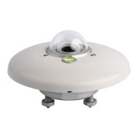
LPS10
- 11 -
V1.0
5 CONFIGURATION
It is possible to change the serial communication parameters (Modbus address, Baud
Rate, parity/stop bit) and, for models with analog output, the type of analog output
and the global irradiance measuring range corresponding to the analog output.
The configuration of the pyranometer can be done:
• With the aid of DATAsense PC application software (see the software online
help), downloadable from Delta OHM website.
• By sending serial commands from a PC, via a standard communication program
(see the chapter “ASCII proprietary protocol”).
• Via the “Holding Registers” in MODBUS-RTU mode (only for the serial communi-
cation parameters, see the chapter “Modbus-RTU protocol”).
By default, the instrument has MODBUS address 1 and communication parameters
19200, 8E1.
Analog output (only LPS10MAx):
By default, the analog output is 4…20 mA → 0…2000 W/m
2
.
It is possible:
• to associate the analog output to a different global irradiance range, within the
full measuring range;
• change the output type (possible outputs 4…20 mA, 0…20 mA, 0…1 V, 0…5 V or
0…10 V);
• to reverse the direction of the output, so that the output decreases as the meas-
urement increases.
Connection to PC:
To connect the pyranometer to a PC USB port, to check or change the configuration,
the CP24B-5 (LPS10M0x) or CP24B-8 (LPS10MAx) optional cables can be used,
which also allow the pyranometer to be powered via the USB port.
To use the CP24B-x cables, the related USB drivers must be installed in the PC.
Alternatively, it is possible to use a standard RS485/USB or RS485/RS232 converter,
powering the pyranometer separately (the minimum supply voltage is 7 V).

 Loading...