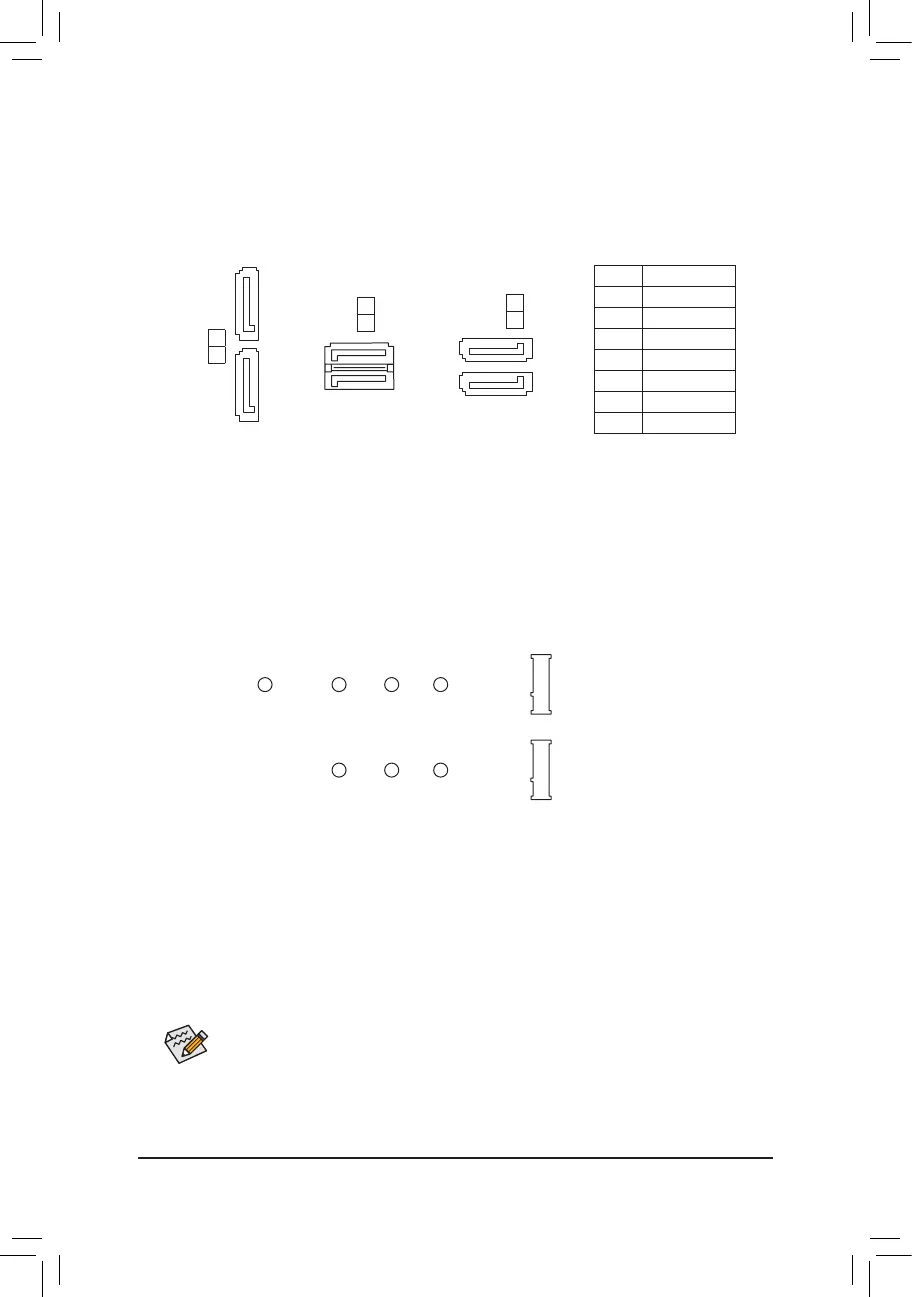
9/10) ASATA3 0/1, SATA 3 0/1/2/3 (SATA 6Gb/s Connectors)
The SATA connectors conform to SATA 6Gb/s standard and are compatible with SATA 3Gb/s and
SATA 1.5Gb/s standard. Each SATA connector supports a single SATA device. The SATA connectors
supportRAID0,RAID1,andRAID10.RefertoChapter3,"ConguringaRAIDSet,"forinstructions
onconguringaRAIDarray.
Pin No. Denition
1 GND
2 TXP
3 TXN
4 GND
5 RXN
6 RXP
7 GND
SATA3
2
3
7
1
7
1
7
1
ASATA3
0
1
SATA3
1
0
7
7
1
1
11) M2A_SOCKET/M2B_SOCKET (M.2 Socket 3 Connectors)
TheM.2connectorssupportM.2SATASSDsorM.2PCIeSSDs
(Note)
andsupportRAIDconguration.
PleasenotethatanM.2PCIeSSDcannotbeusedtocreateaRAIDseteitherwithanM.2SATASSDora
SATAharddrive.TocreateaRAIDarraywithanM.2PCIeSSD,youmustsetupthecongurationinUEFI
BIOSmode.RefertoChapter3,"ConguringaRAIDSet,"forinstructionsonconguringaRAIDarray.
SelecttheproperholefortheM.2SSDtobeinstalledandrefastenthescrewandnut.
F_USB30
F_U
B_
F_ F_
_
B
BS_
B
SB_
B
_S
S_
_
B
_U
_
B
S
123
123
123
123
1
1
1
1
BSS
S
_S
SSU
1 2 3
S3
BSSS
U
__ 3
F_USB3F
S _
S _
S _
SF
B_
B_
F
_0
S
S
_0F
_F
_
_
__B
U
S _S
_
SF_
USB0_B
B_
F_USB3
F_USB303
_
_3U
80110 60 42
F_USB30
F_U
B_
F_ F_
_
B
BS_
B
SB_
B
_S
S_
_
B
_U
_
B
S
123
123
123
123
1
1
1
1
BSS
S
_S
SSU
1 2 3
S3
BSSS
U
__ 3
F_USB3F
S _
S _
S _
SF
B_
B_
F
_0
S
S
_0F
_F
_
_
__B
U
S _S
_
SF_
USB0_B
B_
F_USB3
F_USB303
_
_3U
80 60 42
M2A_SOCKET
M2B_SOCKET
FollowthestepsbelowtocorrectlyinstallanM.2SSDintheM.2connector.
Step 1:
Get a screw and a standoff from the included M.2 screw and standoff packs. Locate the M.2 connector
whereyouwillinstalltheM.2SSD,useascrewdrivertounfastenthescrewontheheatsinkandthen
remove the heatsink.
Step 2:
LocatethepropermountingholefortheM.2SSDtobeinstalledandthentightenthestandoffrst.Insert
theM.2SSDintotheM.2connectoratanangle.
Step 3:
PresstheM.2SSDdownandthensecureitwiththescrew.Replacetheheatsinkandsecureittothe
original hole.
(Note) TheM2B_SOCKETconnectorsupportsonlyPCIeSSDs.
- 16 -
 Loading...