• Be sure to conne ct an cables to the an h eaders to prevent your CPU and system rom
overheating. Overheating may result in damage to the CPU or the system may hang.
• These an headers are not conguration jumper blocks. Do not place a jumper cap on the headers.
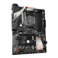
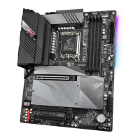
3/4) CPU_FAN/SYS_FAN1/SYS_FAN2 (Fan Headers)
All an headers on this motherboard are 4-pin. Most an headers possess a oolproo insertion design.
When connecting a an cable, be sure to connect it in the correct orientation (the black connector wire
is the ground wire). The motherboard supports CPU an speed control, which requires the use o a CPU
an with an speed control design. For optimum heat dissipation, it is recommended that a system an be
installed inside the chassis.
Pin No. Denition
1 GND
2 Voltage Speed Control
3 Sense
4 PWM Speed Control
5) D_LED1/D_LED2 (Addressable LED Strip Headers)
The headers can be used to connect a standard 5050 addressable LED strip, with maximum power rating
o 5A (5V) and maximum number o 1000 LEDs.
Pin No. Denition
1 V (5V)
2 Data
3 No Pin
4 GND
1
1
D_LED1 D_LED2
C onnect your addre ssable LED
strip to the header. The power pin
(marked with a triangle on the plug)
o the LED strip must be connected
to P in 1 o the addressable LED
strip header. Incorrect connection
may l ead to the damage o th e
LED strip.
Addressable
LED Strip
1
CPU_FAN
1
SYS_FAN1
1
SYS_FAN2
1
Beore installing the devices, be sure to turn o the devices and your computer. Unplug the power
cord rom the power outlet to prevent damage to the devices.
For how to turn on/o the lights o the LED strip please visit the "Unique Features" webpage o
GIGABYTE's website.
- 16 -
 Loading...