131
2412
ATX
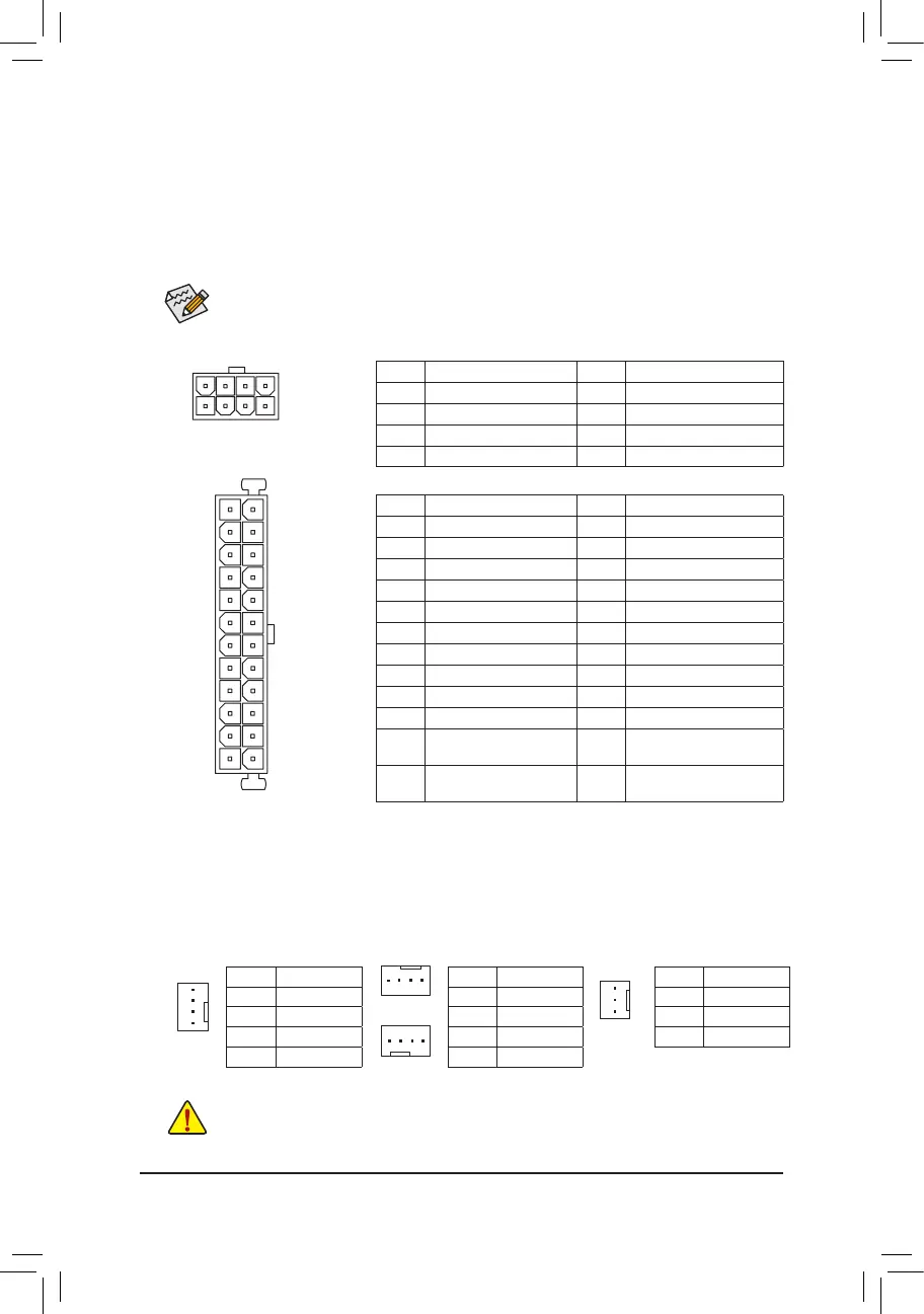
1/2) ATX_12V_2X4/ATX (2x4 12V Power Connector and 2x12 Main Power Connector)
With the use of the power connector, the power supply can supply enough stable power to all the components
onthemotherboard.Beforeconnectingthepowerconnector,rstmakesurethepowersupplyisturned
off and all devices are properly installed. The power connector possesses a foolproof design. Connect the
power supply cable to the power connector in the correct orientation.
The 12V power connector mainly supplies power to the CPU. If the 12V power connector is not connected,
the computer will not start.
To meet expansion requirements, it is recommended that a power supply that can withstand high
power consumption be used (500W or greater). If a power supply is used that does not provide the
required power, the result can lead to an unstable or unbootable system.
ATX:
Pin No. Denition Pin No. Denition
1 3.3V 13 3.3V
2 3.3V 14 -12V
3 GND 15 GND
4 +5V 16 PS_ON (soft On/Off)
5 GND 17 GND
6 +5V 18 GND
7 GND 19 GND
8 Power Good 20 NC
9 5VSB (stand by +5V) 21 +5V
10 +12V 22 +5V
11 +12V (Only for 2x12-pin
ATX)
23 +5V (Only for 2x12-pin ATX)
12 3.3V (Only for 2x12-pin
ATX)
24 GND (Only for 2x12-pin ATX)
3/4) CPU_FAN/SYS_FAN1/SYS_FAN2/SYS_FAN3 (Fan Headers)
The motherboard has a 4-pin CPU fan header (CPU_FAN), two 4-pin (SYS_FAN1, SYS_FAN2) and a 3-pin
(SYS_FAN3) system fan headers. Most fan headers possess a foolproof insertion design. When connecting
a fan cable, be sure to connect it in the correct orientation (the black connector wire is the ground wire).
The speed control function requires the use of a fan with fan speed control design. For optimum heat
dissipation, it is recommended that a system fan be installed inside the chassis.
• Be sure to connect fan cables to the fan headers to prevent your CPU and system from
overheating. Overheating may result in damage to the CPU or the system may hang.
• Thesefanheadersarenotcongurationjumperblocks.Donotplaceajumpercapontheheaders.
SYS_FAN1
1
CPU_FAN:
Pin No. Denition
1 GND
2 +12V
3 Sense
4 Speed Control
SYS_FAN1/SYS_FAN2:
Pin No. Denition
1 GND
2 Speed Control
3 Sense
4 VCC
SYS_FAN3:
Pin No. Denition
1 GND
2 +12V
3 Sense
SYS_FAN2
SYS_FAN3
CPU_FAN
1
1
1
ATX_12V_2X4:
Pin No. Denition Pin No. Denition
1 GND (Only for 2x4-pin 12V) 5 +12V (Only for 2x4-pin 12V)
2 GND (Only for 2x4-pin 12V) 6 +12V (Only for 2x4-pin 12V)
3 GND 7 +12V
4 GND 8 +12V
ATX_12V_2X4
41
85
- 13 -
 Loading...