- 16 -
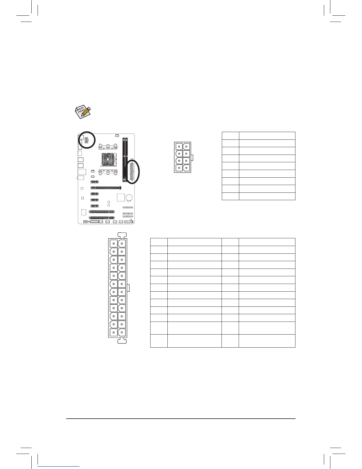
1/2) ATX_12V/ATX (2x4 12V Power Connector and 2x12 Main Power Connector)
With the use of the power connector, the power supply can supply enough stable power to all the components
onthemotherboard.Beforeconnectingthepowerconnector,rstmakesurethepowersupplyisturned
off and all devices are properly installed. The power connector possesses a foolproof design. Connect the
power supply cable to the power connector in the correct orientation.
The 12V power connector mainly supplies power to the APU. If the 12V power connector is not connected,
the computer will not start.
To meet expansion requirements, it is recommended that a power supply that can withstand high
powerconsumptionbeused(500Worgreater).Ifapowersupplyisusedthatdoesnotprovidethe
required power, the result can lead to an unstable or unbootable system.
131
24
12
ATX
ATX:
Pin No. Denition Pin No. Denition
1 3.3V 13 3.3V
2 3.3V 14 -12V
3 GND 15 GND
4 +5V 16 PS_ON(softOn/Off)
5 GND 17 GND
6 +5V 18 GND
7 GND 19 GND
8 Power Good 20 -5V
9 5VSB(standby+5V) 21 +5V
10 +12V 22 +5V
11 +12V(Onlyfor2x12-pin
ATX)
23 +5V(Onlyfor2x12-pinATX)
12 3.3V(Onlyfor2x12-pin
ATX)
24 GND(Onlyfor2x12-pin
ATX)
ATX_12V:
Pin No. Denition
1 GND(Onlyfor2x4-pin12V)
2 GND(Onlyfor2x4-pin12V)
3 GND
4 GND
5 +12V(Onlyfor2x4-pin12V)
6 +12V(Onlyfor2x4-pin12V)
7 +12V
8 +12V
ATX_12V
 Loading...