- 17 -
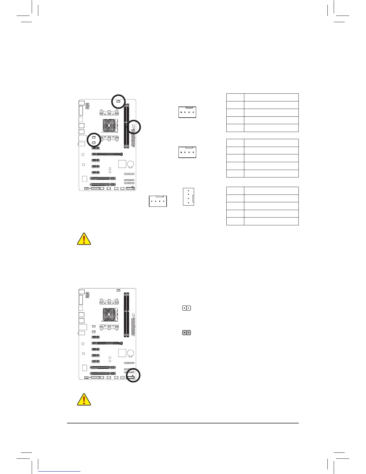
3/4)CPU_FAN/SYS_FAN1/SYS_FAN2/SYS_FAN3(FanHeaders)
All fan headers on this motherboard are 4-pin. Most fan headers possess a foolproof insertion design.
Whenconnectingafancable,besuretoconnectitinthecorrectorientation(theblackconnectorwireis
thegroundwire).Thespeedcontrolfunctionrequirestheuseofafanwithfanspeedcontroldesign.For
optimum heat dissipation, it is recommended that a system fan be installed inside the chassis.
• Be sure to connect fan cables to the fan headers to prevent your APU and system from
overheating. Overheating may result in damage to the APU or the system may hang.
• Thesefanheadersarenotcongurationjumperblocks.Donotplaceajumpercapontheheaders.
CPU_FAN
1
CPU_FAN:
Pin No. Denition
1 GND
2 +12V /Speed Control
3 Sense
4 Speed Control
SYS_FAN1:
Pin No. Denition
1 GND
2 +12V /Speed Control
3 Sense
4 Reserve
5) CLR_CMOS(ClearCMOSJumper)
UsethisjumpertocleartheCMOSvalues(e.g.dateinformationandBIOScongurations)andresetthe
CMOSvaluestofactorydefaults.TocleartheCMOSvalues,useametalobjectlikeascrewdrivertotouch
the two pins for a few seconds.
Open: Normal
Short: Clear CMOS Values
• Always turn off your computer and unplug the power cord from the power outlet before clearing
the CMOS values.
• Aftersystemrestart,gotoBIOSSetuptoloadfactorydefaults(selectLoadOptimizedDefaults)or
manuallyconguretheBIOSsettings(refertoChapter2,"BIOSSetup,"forBIOScongurations).
SYS_FAN1
 Loading...