- 10 -
Hardware Installation
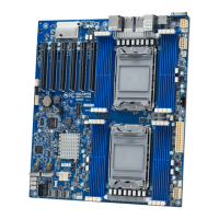
Socket
Socket
Security
Security
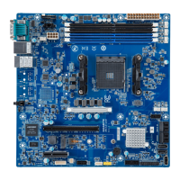
Internal I/O
Connectors
1 x 24-pin ATX main power connector
1 x 8-pin ATX 12V power connector
6 x SATA ports
1 x M.2 slot
1 x HDD back plane board header
1 x CPU fan header
5 x System fan headers
1 x USB 3.1 Gen1 header with 2-port
1 x USB 3.1 Gen1 type-A connector
1 x USB 2.0 header with 2-port
1 x TPM header
1 x Front panel header
1 x IPMB connector
1 x PMBUS connector
1xClearCMOSjumper
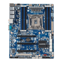
Socket
Socket
Security
Security
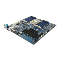
Rear I/O
Connectors
2 x USB 3.1 Gen1
1 x VGA
1 x COM
2 x RJ45
1 x MLAN
1 x ID button with LED
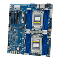
Socket
Socket
Security
Security
TPM
1 x TPM Header with SPI Interface
Optional TPM2.0 kit: CTM010
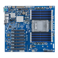
Socket
Socket
Security
Security
Board
Management
Aspeed® AST2500 Management Controller
GIGABYTE Management Console (AMI MegaRAC SP-X) Web Interface
Socket
Socket
Security
Security
Operating
Properties
Operating temperature: 10°C to 40°C
Operating humidity: 8-80% (non-condensing)
Non-operating temperature: -40°C to 60°C
Non-operating humidity: 20%-95% (non-condensing)
Socket
Socket
Security
Security
 Loading...