- 19 -
Hardware Installation
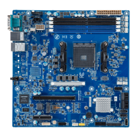
7) PMBus Connector
The Power Management Bus (PMBus) is a variant of the System Management Bus (SMBus) which is
targeted at digital management of power supplies.
5
PinNo. Denition
1 PMBus Clock
2 PMBus Data
3 PMBus Alert
4 GND
5 3.3V Sense
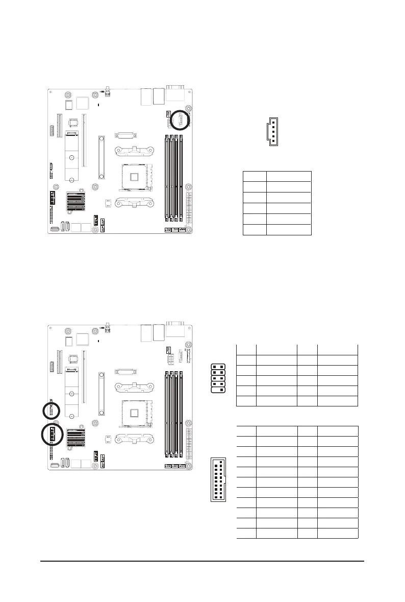
8/9) F_USB3_1/F_USB2_1 (Front Panel USB 3.1/2.0 Connector)
The header conform to USB 3.1/2.0 specification. Each USB header can provide two USB ports via an
optional USB bracket. For purchasing the optional USB bracket, please contact the local dealer.
USB 2.0 Header
USB 3.1 Connector
Pin No. Denition Pin No. Denition
1 Power 11 IntA_P2_D+
2 IntA_P1_SSRX- 12 IntA_P2_D-
3 IntA_P1_SSRX+ 13 GND
4 GND 14 IntA_P2_SSTX+
5 IntA_P1_SSTX- 15 IntA_P2_SSTX-
6 IntA_P1_SSTX+ 16 GND
7 GND 17 IntA_P2_SSRX+
8 IntA_P1_D- 18 IntA_P2_SSRX-
9 IntA_P1_D+ 19 Power
10 NC 20 No Pin
Pin No. Denition Pin No. Denition
1 Power (5V) 6 USB DY+
2 Power (5V) 7 GND
3 USB DX- 8 GND
4 USB DY- 9 No Pin
5 USB DX+ 10 No Connect
1 2
9 10
120
11 10
 Loading...