- 6 -
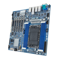
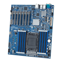
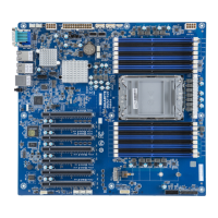
Item Code Description
1 LED_BMC BMC Firmware Readiness LED
2 CN_NCSI NCSI Connector
3 SYS_FAN6 System Fan Connector #6
4 P12V_AUX2 2x4 Pin 12V Power Connector
5 MLAN Server Management LAN Port
6 USB3_LAN1 1GbE LAN Port #1 (Top)/USB 3.2 Gen1 Ports (Bottom)
7 USB3_LAN2 1GbE LAN Port #2 (Top)/USB 3.2 Gen1 Ports (Bottom)
8 COM1_VGA Serial Port (Top)/VGA Port (Bottom)
9 SW_ID ID Button with LED
10 P12V_AUX1 2x4 Pin 12V Power Connector
11 ATX1 2x12 Pin Main Power Connector
12 PMBUS PMBus Connector
13 CPU0_FAN CPU Fan Connector
14 BAT Battery Socket
15 SYS_FAN5 System Fan Connector #5
16 M2_0 M.2 Slot (PCIe Gen3 x4, Support NGFF-2280/22110)
17 SL_SATA3 Slimline Connector #3 (SATA 6Gb/s Signal)
18 SL_SATA2 Slimline Connector #2 (SATA 6Gb/s Signal)
19 SL_SATA1 Slimline Connector #1 (SATA 6Gb/s Signal)
20 SYS_FAN4 System Fan Connector #4
21 SYS_FAN2 System Fan Connector #2
22 SYS_FAN1 System Fan Connector #1
23 SYS_FAN3 System Fan Connector #3
24 F_USB1 Front Panel USB 3.2 Gen1 Connector
25 FP_1 Front Panel Header
26 SPI_TPM TPM Connector
27 BP_1 HDD Backplane Board Connector
28 IPMB IPMB Connector
29 CASE_OPEN Case Open Intrusion Alert Header
30 PCIE_1 PCIe x16 Slot #1 (Gen5 x8)
31 PCIE_2 PCIe x16 Slot #2 (Gen5 x16)
32 PCIE_3 PCIe x16 Slot #3 (Gen5 x8)
33 PCIE_4 PCIe x16 Slot #4 (Gen5 x16)
34 PCIE_5 PCIe x16 Slot #5 (Gen5 x16)
35 PCIE_6 PCIe x16 Slot #6 (Gen5 x16)
36 PCIE_7 PCIe x16 Slot #7 (Gen5 x16)