The front panel design may differ by chassis. A front panel module mainly consists of power switch,
reset switch, power LED, hard drive activity LED, speaker and etc. When connecting your chassis
front panel module to this header, make sure the wire assignments and the pin assignments are
matched correctly.
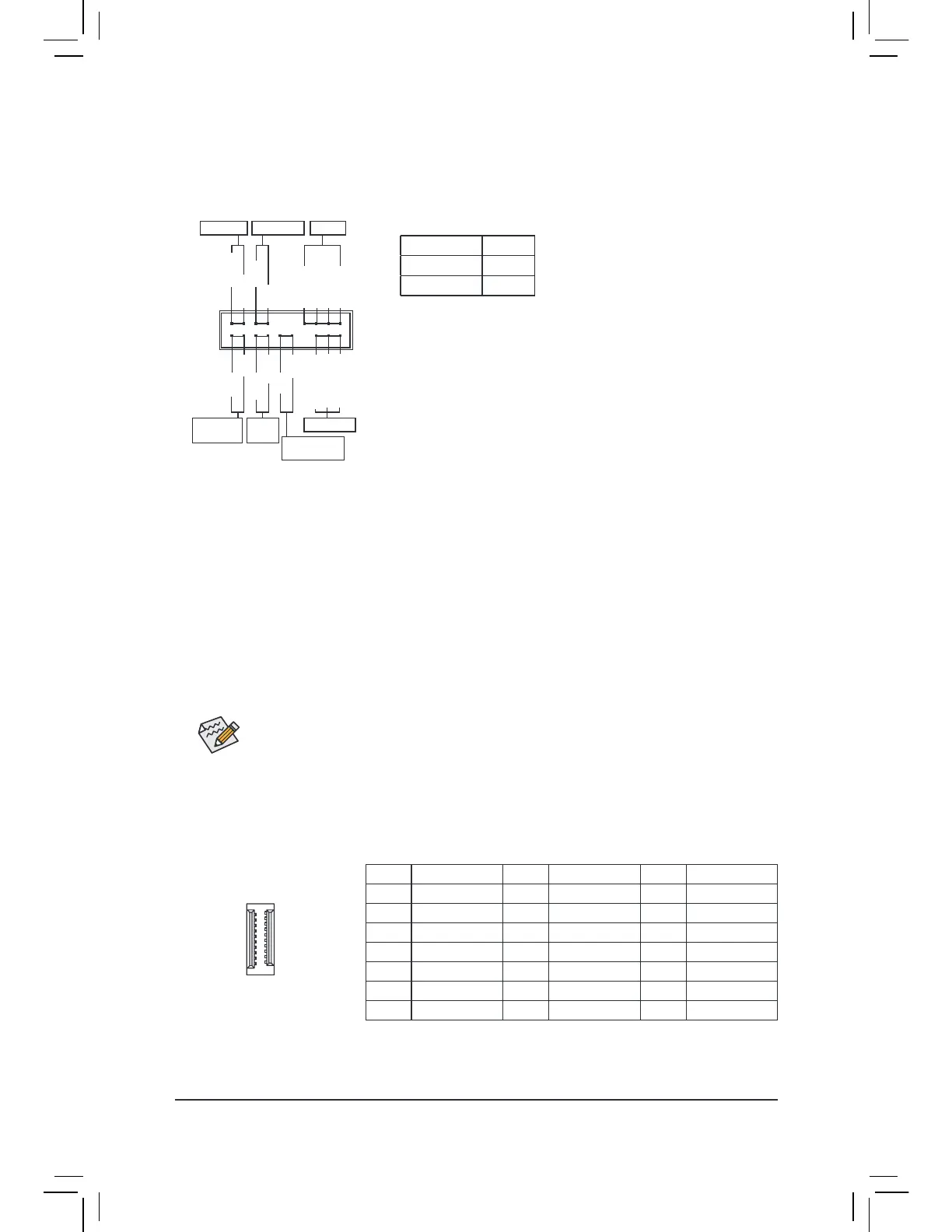
12) F_PANEL (Front Panel Header)
Connect the power switch, reset switch, speaker, chassis intrusion switch/sensor and system status indicator
on the chassis to this header according to the pin assignments below. Note the positive and negative pins
before connecting the cables.
System Status LED
S0 On
S3/S4/S5 Off
• PW (Power Switch):
Connects to the power switch on the chassis front panel. You may
congure the way to turn o your system using the power switch
(reer to Chapter 2, "BIOS Setup," "Settings\Platorm Power," or more
information).
• SPEAK (Speaker):
Connects to the speaker on the chassis front panel. The system reports
system startup status by issuing a beep code. One single short beep
will be heard if no problem is detected at system startup.
• PLED/PWR_LED (Power LED):
Conne cts to the power status indicator
on the chassis ront panel. The LED is on
when the system is operating. The LED is
off when the system is in S3/S4 sleep state
or powered off (S5).
• HD (Hard Drive Activity LED):
Connects to the hard drive activity LED on the chassis ront panel. The LED is on when the hard drive
is reading or writing data.
• RES (Reset Switch):
Connects to the reset switch on the chassis front panel. Press the reset switch to restart the computer
i the computer reezes and ails to perorm a normal restart.
• CI (Chassis Intrusion Header):
Connects to the chassis intrusion switch/sensor on the chassis that can detect if the chassis cover has
been removed. This function requires a chassis with a chassis intrusion switch/sensor.
• NC: No Connection.
Power LED
1
2
19
20
CI-
CI+
PWR_LED-
PWR_LED+
PLED-
PW-
SPEAK+
SPEAK-
PLED+
PW+
Power LED
HD-
RES+
HD+
RES-
Hard Drive
Activity LED
Reset
Switch
Chassis
Intrusion Header
Power Switch Speaker
PWR_LED-
NC
NC
13) F_USB31C (USB Type-C
™
Header with USB 3.2 Gen 2 Support)
The header conorms to USB 3.2 Gen 2 specication and can provide one USB port.
Pin No. Denition Pin No. Denition Pin No. Denition
1 VBUS 8 CC1 15 RX2+
2 TX1+ 9 SBU1 16 RX2-
3 TX1- 10 SBU2 17 GND
4 GND 11 VBUS 18 D-
5 RX1+ 12 TX2+ 19 D+
6 RX1- 13 TX2- 20 CC2
7 VBUS 14 GND
20
10 11
1
- 21 -
 Loading...