7.5.15 Debug Parameter
This function is used for manufacturer maintenance personnel only.
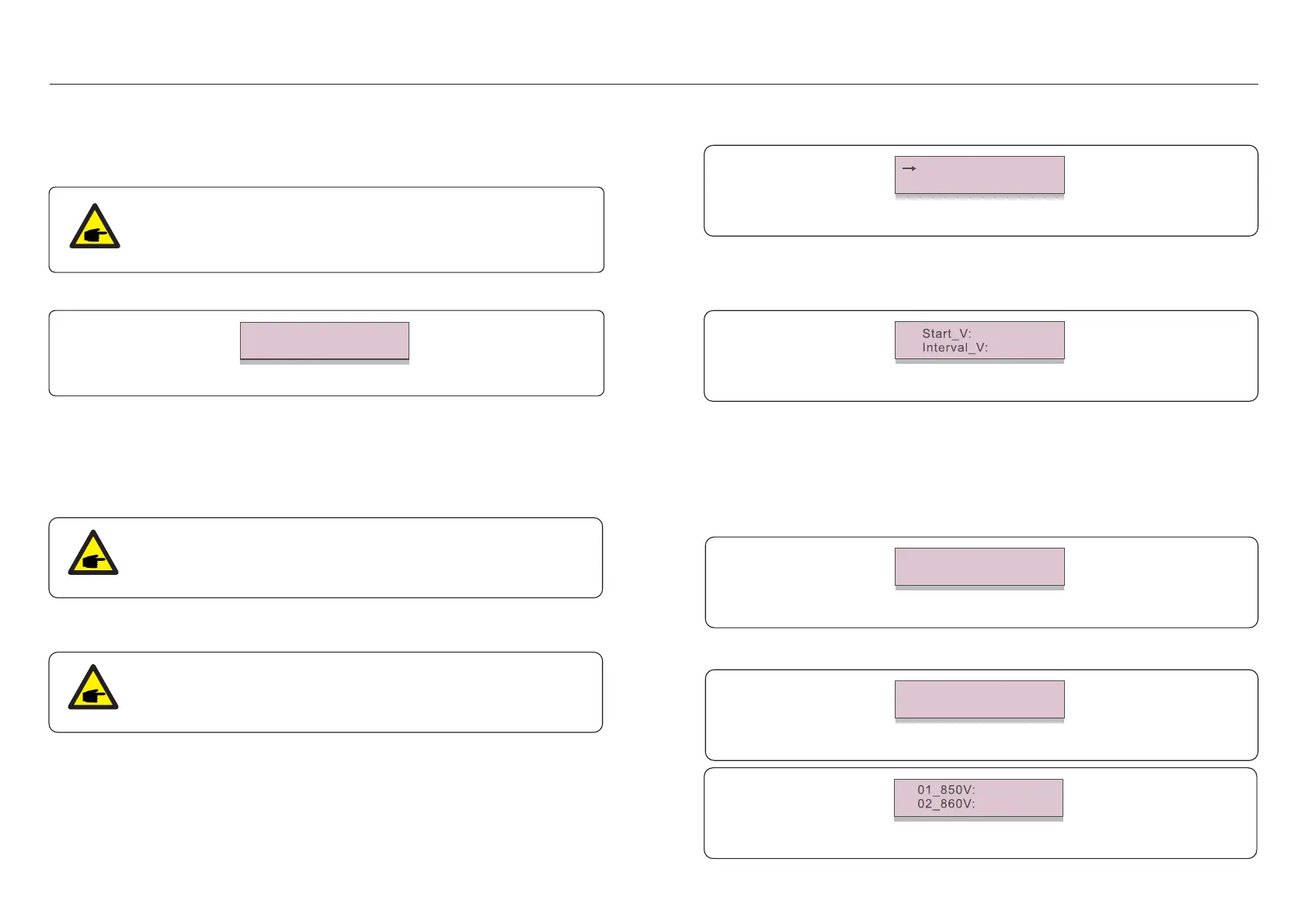
7. Operation7. Operation
7.5.19.2 I/V Curve Scan
Press “ENT” to start the I/V curve scan.
Figure 7.34 I/V Curve Scan (1)
Scanning...01
After it is completed, the screen will display “Scan OK” and then enter the following section.
Figure 7.35 I/V Curve Scan (2)
Select String No.: 01
Figure 7.36 I/V Curve Scan (3)
9.56A
9.44A
.43..42.
7.5.16 FAN Test
This section is applicable to maintenance personnel only.
Figure 7.31
Selecting “Fan Test” displays the sub-menu shown below:
Are you sure?
YES=<ENT> NO=<ESC>
Fan Test is a factory test function. Press the ENTER key to start the test.
Press the ESC key to return to the previous menu.
7.5.17 DSP Update
The function is used for update the DSP.
This function is applicable by maintenance personnel only, wrong operation
will prevent the inverter from reaching maximum power.
7.5.18 Compensation Set
This function is applicable by maintenance personnel only, wrong operation
will prevent the inverter from reaching maximum power.
7.5.19 I/V Curve
This function is used to scan the I/V characteristic curves of each PV strings.
Figure 7.32 I/V Curve
Set I/V Curve
I/V Curve Scan
7.5.19.1 Set I/V Curve
This setting can set the scanning voltage start point and the voltage interval.
Figure 7.33 Set I/V Curve
850V
010V
Start_V: The start voltage of the I/V scan. (Adjustable from 300V-1000V)
Interval_V: The scanning voltage interval.(Adjustable from 1-100V)
In total, 60 data points can be scanned.
 Loading...