
M
Maria MartinezSep 10, 2025
How to fix OV-BUS error on Ginlong Solis 5G Inverter?
- SSara CainSep 10, 2025
If your Ginlong Inverter displays OV-BUS, check the inverter inductor connection and the driver connection.
How to fix OV-BUS error on Ginlong Solis 5G Inverter?
If your Ginlong Inverter displays OV-BUS, check the inverter inductor connection and the driver connection.
How to troubleshoot a Ginlong Inverter with no power?
If your Ginlong Inverter has no power, check the PV input connections, ensure the DC input voltage is higher than 620V, and verify that the PV+/- is not reversed.
What causes OV-TEM error on Ginlong Solis 5G Inverter and how to fix it?
If your Ginlong Inverter shows OV-TEM, check the inverter's surrounding ventilation and ensure there is no direct sunshine on the inverter during hot weather.
What to do if my Ginlong Solis 5G displays OV-DC01/02/03/04 error?
If your Ginlong Inverter displays OV-DC01/02/03/04, reduce the number of modules in series.
How to fix arcing protection on Ginlong Inverter?
If the arcing protection is activated on your Ginlong Inverter (model with AFCI module), check the inverter connection for any arc and restart the inverter.
What does OV-G-V01/02/03/04 mean on a Ginlong Solis 5G Inverter?
If your Ginlong Inverter displays OV-G-V01/02/03/04, it may be due to high resistance in the AC cable. Try changing to a larger size grid cable. If allowed by your electrical company, you can also adjust the protection limit.
What does RelayChk-FAIL error mean on a Ginlong Solis 5G Inverter?
If your Ginlong Inverter displays RelayChk-FAIL, restart the inverter or contact installer.
What causes GRID-INTF01/02 error on a Ginlong Inverter?
If your Ginlong Inverter displays GRID-INTF01/02, try restarting the inverter. If the problem persists, consider changing the power board.
What does DC-INTF OV-DCA-I error mean on Ginlong Solis 5G Inverter?
If your Ginlong Inverter displays DC-INTF OV-DCA-I, restart the inverter. Identify and remove the string to the fault MPPT. If the issue persists, consider changing the power board.
Why does my Ginlong Solis 5G Inverter LCD show initializing all the time?
If the LCD on your Ginlong Inverter shows 'initializing' continuously, check if the connectors on the main board or power board are securely fixed. Also, check if the DSP connector to the power board is properly connected.
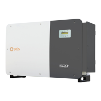
Overview of Solis three-phase transformerless grid support PV inverters.
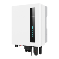
Details the front panel interface of the inverter, including display and buttons.
Explains the meaning of the POWER, OPERATION, and ALARM LEDs on the inverter.
Lists the parts included with the inverter for unpacking and verification.
Provides a schematic diagram of the inverter's internal electrical circuitry.
Lists necessary tools for the proper installation of the inverter.
Outlines proper storage instructions and environmental conditions for the inverter.
Provides guidance on the environmentally responsible disposal of the product.
Explains the meaning of various safety symbols used throughout the manual.
Provides essential safety guidelines and warnings for installation and operation.
Specifies conditions and limitations for using the inverter according to safety guidelines.
Details built-in protection features like AFCI and Anti-Islanding protection.
Discusses location requirements, temperature, humidity, and load bearing structure for installation.
Instructions for safely moving and handling the inverter, requiring two people and specific handles.
Details how to mount the inverter on a wall or racking, including dimensions and mounting holes.
Explains DC and AC electrical connections, including terminal types, wire sizes, and torque specifications.
Describes the methods for grounding the inverter, including cable preparation and terminal connection.
Instructions and warnings for connecting the PV side of the inverter using MC4 terminals.
Details connecting the AC conductors to the grid terminals and the grounding conductor.
Guidelines for using aluminum cables with adapter terminals to prevent corrosion.
Emphasizes compliance with local standards and codes for grid connection.
Outlines the steps for wiring, including safety precautions for AC terminals.
Explains how to set up a monitoring system using RS-485 daisy chain configuration for multiple inverters.
Describes the setup for a multiple inverter monitoring system using PLC communication.
Importance of verifying the grid standard for the installation country before commissioning.
Procedure for service technicians to change or set the grid standard.
Instructions for creating a custom grid configuration, requiring technician access and approval.
Lists checks for DC/AC connections, DC configuration, and leakage to ground before operation.
Details verifying AC configuration, measuring VAC, frequency, and phase rotation tests.
Step-by-step guide for safely starting up the inverter following all checks.
Step-by-step guide for safely shutting down the inverter, including safety waiting periods.
Overview of the four submenus available in the main menu.
Accessing operational data like voltage, current, power, energy, and serial number.
How to lock and unlock the inverter's LCD screen using ESC and ENTER keys.
Submenus for setting time, date, and inverter address for datalogger connection.
Accessing alarm messages, running status, version, energy data, and communication data.
Access to configuration and operational parameters for qualified technicians.
Function to select the grid's reference standard or create a custom standard.
Enables starting or stopping power generation and controlling reactive power compensation.
Resets the inverter's historical energy yield data.
Allows setting a new password for accessing advanced menus.
Configuration of active and reactive power settings, including output power and power factor.
Function to revise total energy values to match previous readings or monitoring website data.
Reserved for maintenance personnel; incorrect settings can prevent maximum power output.
Accesses sub-menus for setting working modes, power limits, frequency derating, and voltage parameters.
Configuration of inverter working modes based on selected grid standards (UL, Rule21).
Sets the power ramp-up rate when the inverter starts up or MPPT changes.
Configures frequency derating settings applicable when UL standards are selected.
This function is disabled and not used for the US market.
Sets the priority between Active Power Control (Watt) and Reactive Power Control (Var).
Resets all work modes from 6.5.8.1 to 6.5.8.4 back to their default values.
Sets the voltage at the Point of Common Coupling (PCC) as required by RULE 21.
Restores all items in the special setting submenu to their default values.
Process for updating the inverter's LCD firmware via a USB stick.
Manually resets the HMI screen by pressing a specific key combination.
A factory test function to check the operation of the inverter's fans.
Process for updating the inverter's DSP firmware via a USB stick.
Used to calibrate inverter output energy and voltage parameters.
Function to scan and display I/V characteristic curves for each PV string.
Details on enabling and managing the built-in DC Arc-Fault Circuit Protection (AFCI).
Explanation of the optional Anti-PID module that recovers PID effect to protect the PV system.
Step-by-step instructions for replacing a damaged or broken inverter fan.
Lists common alarm messages, failure descriptions, and their corresponding solutions.
Detailed technical specifications for the Solis-185K-EHV-5G-US inverter model.
Detailed technical specifications for the Solis-255K-EHV-5G-US inverter model.
Detailed technical specifications for the Solis-125K-EHV-5G-US-PLUS inverter model.
Detailed technical specifications for the Solis-185K-EHV-5G-US-PLUS inverter model.
Detailed technical specifications for the Solis-255K-EHV-5G-US-PLUS inverter model.
Graphs showing output power derating based on ambient temperature for different models.
Graphs illustrating output power derating based on DC input voltage and temperature.
Graphs showing output power derating based on AC grid voltage and temperature.
P-Q capability curves at nominal output power and varying grid voltage conditions.
Table listing default grid protection settings for the UL-600-18 standard.
Table listing default grid protection settings for the UL-800-18 standard.
Certificate showing CSA compliance for various Solis inverter models.
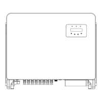
Provides mechanical dimensions and installation layout drawings for the inverter.
Diagrams illustrating compatible transformer winding configurations and their applicability.
| Topology | Transformerless |
|---|---|
| Number of MPPTs | 2 |
| THDi | <3% |
| Enclosure Rating | IP65 |
| Max. Efficiency | 98.4% |
| Communication | WiFi |
| Operating Temperature Range | -25°C ~ +60°C |
| Cooling | Natural convection |
| AC Voltage Range | 180-280 V |
| Frequency | 50/60 Hz |
| Output Power | 5 kW |
| Nominal AC Output Power | 5 kW |
| Max. AC Output Current | 22 A |