User Manual
3.4 Electrical Connections
The electrical connection of the inverter must follow the steps listed below:
1. Switch the Grid Supply Main Switch (AC) OFF and LOTO the AC Switch.
2. Switch the DC Switch OFF.
3. Connect the inverter to the grid.
4. Assemble PV connector and connect to the Inverter.
Inverter design uses PV style quick-connect terminal. The top cover does not need be opened
during DC electrical connection. The labels located the bottom of the inverter are described
below in table 3.1. All electrical connections are suitable for local and national standard.
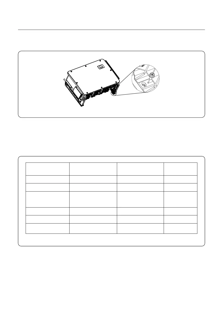
Table 3.1 Electrical connection specification
Cable
Connection Cable size
Torque
DC terminal
Ground terminal
Grid terminal
RS-485 terminal
COM terminal
PV strings
AC ground
Grid
Communication cable
Wi-Fi/Cellular stick
12-10 AWG
2-4/0 AWG
1/0 AWG-600 MCM
(Max 600MCM)
20-18 AWG
NA
7.4-8.9 ft.lbs
17-21 ft.lbs
0.44 ft.lbs
NA
DC surge protection
device
NA NANA
NA
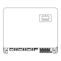
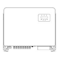
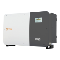
Figure 3.9 Fix the inverter
5. Use screws in the packaging to fix the inverter to the mounting bracket.
Torque:1.5-2.2 ft.lbs
3. Installation
17
 Loading...