EasyManua.ls Logo

Glacier bay GBTO102 User Manual

Glacier bay GBTO102
7 pages
To Next Page IconTo Next Page
Page #1 background imageLoading...
Page #1 background image
GBTO102
INSTALLATION MANUAL | MANUEL D’INSTALLATION | MANUAL DE INSTALACIÓN
Measures: inch [millimeter]
Mesures: pouce [millimètre]
Medidas: pulgadas [milímetros]
Flush | Chasse | Descarga
1.28 gal | 4.8 L
6” [150]
28 3/4” [730]
18 5/16” [465]
12 7/8” [326]
17 7/8” [454]
17 1/2” [445]
28” [710]
28 1/8” [715]
14” [355]
28 1/8” [715]
17 1/2” [445]
6 11/16” [170]
12” [305]
6” [150]
ø2” [ø51]
ø3 3/8” [ø85]
19 7/8” [505]
28” [710]
11 1/4” [285]
5 1/2” [141]
7/8” [22]
18 1/4” [464]
9 13/16” [250]
Questions, problems, need help?
Call our customer service department at
1-855-HDGLACIER(1-855-434-5224)
Questions, problèmes ou besoin d’aide?
Contactez notre service à la clientèle au
1-855-HDGLACIER(1-855-434-5224)
Preguntas, problemas o necesita ayuda?
Llame a nuestro departamento de servicio al cliente al
1-855-HDGLACIER(1-855-434-5224)
1/2” [12]
Question and Answer IconNeed help?

Do you have a question about the Glacier bay GBTO102 and is the answer not in the manual?

Glacier bay GBTO102 Specifications

General IconGeneral
BrandGlacier bay
ModelGBTO102
CategoryToilets
LanguageEnglish

Summary

Part List and Tools

Parts List

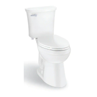
Details components of the Glacier Bay toilet, including part numbers and descriptions.

Required Tools

Lists tools needed for installation that are not supplied with the product.

Installation Step 1: Floor Preparation

Ensure proper water and drain setup.

Verify water inlet pipe and floor discharge drain installation meets minimum measurements.

Install floor flange.

Follow manufacturer's recommendations for installing the floor flange.

Secure flange bolts.

Position and immobilize floor flange bolts using provided plastic nuts.

Attach seal ring.

Firmly push the seal ring onto the toilet's drain to fix it to the ceramic.

Installation Step 2: Toilet Mounting

Align toilet with flange bolts.

Position the toilet onto the floor flange, aligning fixing bolts with toilet holes.

Tighten fixing bolts.

Use an adjustable wrench to screw nuts tightly onto fixing bolts.

Connect fill valve tube.

Connect the fill valve water tube to the flush valve as indicated.

Installation Step 3: Seat Installation

Install seat cover hardware.

Attach seat cover hardware and decorative caps, adjusting pegs for desired position.

Secure toilet seat.

Insert the seat onto the toilet by pushing buttons and securing to fixing pegs.

Adjusting Water Tank Level

Adjust float height.

Rotate the fill valve's adjustable rod to set the float height.

Care and Maintenance

Repairs

Information on obtaining replacement parts from plumbing retailers.

Maintenance and Care

Guidelines for general cleaning using mild soap and warm water, avoiding abrasives.

Limited Product Warranty

Warranty Claim Procedure

Steps to make a claim by contacting customer service for troubleshooting and resolution.

Disclaimer and Exclusion of Warranties

Details limitations and exclusions of warranties, including implied warranties.

Limitation and Exclusion of Remedies and Damages

Outlines DISTRIBUTOR's sole responsibility and limitations on incidental or consequential damages.

Related product manuals