6.0 SYSTEM DETAILS
6.4 SYSTEM FILLING AND PRESSURISING
1. A filling point connection on the central heating return
pipework must be provided for initial filling and pressurising
and subsequent topping up of the system.
A filling loop is provided loose with the boiler
2. The filling method adopted must comply with all relevant
water supply regulations and use approved equipment.
3. Further details are given in;
for GB: Guidance G24.2 and recommendation R24.2 of the
Water Regulations Guide.
for IE: the current edition of I.S. 813 “Domestic Gas
Installations”.
4. The sealed primary circuits may be filled or topped up using
a temporary connection between the circuit and a supply pipe,
provided a ‘Listed’ double check valve or some other no less
effective backflow prevention device is permanently connected
at the inlet to the circuit and the temporary connection is
removed after use.
1. The appliance expansion vessel is pre-charged to 1 bar.
Therefore the minimum cold fill pressure is 2 bar. The vessel is
suitable for correct operation for system capacities up to 84
litres. For greater system capacities an additional expansion
vessel must be fitted.
For GB refer to BS 7074 Pt 1.
For IE, the current edition of I.S. 813 “Domestic Gas
Installations”.
6.6 PRESSURE RELIEF VALVE
1. The pressure relief valve is set at 3 bar, therefore all
pipework, fittings, etc. should be suitable for pressures in
excess of 3 bar and temperature greater than 100°C.
2. The pressure relief discharge pipe should be not less than
15mm diameter, run continuously downward, and discharge
outside the building, preferably over a drain. It should be
routed in such a manner that no hazard occurs to occupants or
causes damage to wiring or electrical components. The end of
the pipe should terminate facing down and towards the wall.
NOTE: Boiling water/steam could discharge from the pipe,
therefore it s
hould be terminated away from windows and
doors.
Mains
Supply
CH
Return
Pressure
Relief
Discharge
Pipe
Temporary
Loop
Stop
Val ve
Stop
Val ve
Double
Check
Val ve
GasCH
Flow
Condensate
1
0123456789101112131415161718
2
3
4
5
6
7
FLOW RATE Ltr/min
PUMP HEAD (mH
2
O)
System 18
System 30
AVAILABLE PUMP HEADS
Expansion Vessel
Pressure
Relief Valve
Vessel charge and initial
system pressure
Total water content of
system using 8 litres
capacity expansion
vessel supplied with
appliance
For systems having a
larger capacity multiply
the total system capacity
in litres by this factor to
obtain the total minimum
expansion vessel capacity
required in litres
bar
litres
0.5
96
0.75
84
0.093
1.0
73
1.5
50
Fig. 6
Fig. 9
Fig. 10
NOTE: Do not use the pressure relief valve to drain the system, because dirt
and debris could preven
t the valve seating correctly.
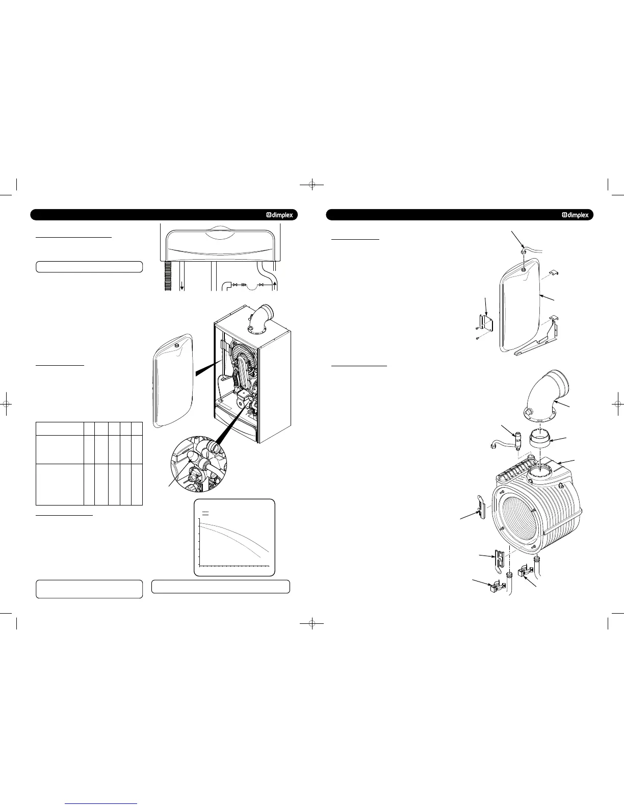
1. Drain the primary circuit and undo the nut on the vessel
connection pipe.
2. Remove the two screws holding the retaining bracket and
remove the bracket (Fig. 67).
3. Carefully slide out the vessel from the boiler.
4. Reassemble in reverse order.
Expansion Vessel
Vessel Connection Pipe
Retaining
Bracket
Flue Elbow
Flue Adaptor
Main Heat
Exchanger
Left Hand
Retaining Bracket
Right Hand
Retaining Bracket
Flow Pipe
Retaining Clip
Return Pipe Retaining Clip
Manual Air Vent
13.17 MAIN HEAT EXCHANGER
1. Drain the primary circuit.
2. Remove the electrode leads, noting their positions as
described in section 13.2.
3. Remove the valve and fan assembly as described in Section
13.3.
4. Examine the gasket and replace if necessary.
5. Undo the four nuts securing the burner door and remove the
cover plate from the heat exchanger.
6. Remove the two clips from the flow and return pipes on the
bottom of the heat exchanger and slide out the pipes (Fig. 68).
7. Remove the clip holding the manual air vent and remove the
pipe from the top of the heat exchanger.
8. Remove the four screws holding the left and right hand
retaining brackets and remove the brackets.
9. Remove the four screws securing the flue to the top of the
boiler. Lift the flue adaptor out of the flue outlet in the top of
the heat exchanger.
10. Carefully slide the heat exchanger out of the boiler.
11. Reassemble in reverse order.
751262 MANUAL 19/10/10 08:41 Page 12
 Loading...

