13.0 CHANGING COMPONENTS
13.18 PCB
1. Ensure supply voltage is fully isolated.
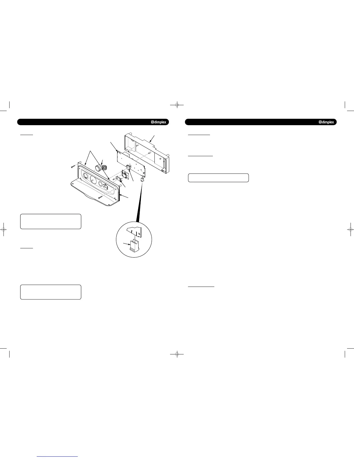
2. Undo the screws holding the control box and gently ease
the box forward (Fig. 69).
3. Locate the retaining barbs on the top of the fascia and
unclip them from the control box.
4. Unclip the PCB from the plastic control box.
5. Note the positions of all the connections on the PCB
and disconnect them.
(DO NOT REMOVE THE YELLOW BCC (Fig. 69))
6. Carefully unclip and remove the ribbon cable
from the PCB and withdraw.
7. Fit all the connection plugs to the new PCB
including the ribbon cable, take care not to damage
the PCB.
8. Unless specifically instructed
to do so by the Dimplex
Service Department, always fit the new BCC if supplied with
the replacement PCB.
Always double check the label on the BCC card to
ensure it is the correct BCC for the boiler model to which it
is being fitted.
NEVER FIT AN INCORRECT BCC.
9. Reassemble in reverse order, ensuring that the control knob
are reset to their previous positions
1. Ensure supply voltage is fully isolated.
2. Dismantle the control box as described above to gain access
to the PCB (Fig. 69).
3. Note the orientation of the existing BCC (if fitted) and
carefully remove by sliding it off the edge of the PCB.
4. Re-fit the new BCC by sliding it onto the edge of the PCB,
ensuring the orientation is correct.
Always double check the label on the BCC card to
ensure it is the correct BCC for the boiler model to which it
is being fitted.
NEVER FIT AN INCORRECT BCC.
5. Reassemble as above.
6. Power up boiler, and briefly press the reset button, wait for
at least 5 seconds and then briefly press the reset button
again.
7. The boiler should now be checked for correct operation.
PCB
Facia
Control Box
Retaining Barbs
Pressure
Gauge
User Interface
Control Knob
6.0 SYSTEM DETAILS
6.1 INFORMATION
1. The Dimplex System Boiler is a ‘Water Byelaws Scheme -
Approved Product’. Reference to the Water Research Council
publications, ‘Water fittings and materials directory’ and ‘Water
supply byelaws guide’ give full details of byelaws and the IRNs.
© Dimplex Boilers 2008
1. It is recommended that external controls e.g. room
thermostat are fitted to further improve the operating
efficiency of the boiler and system.
1. The appliance is suitable for fully pumped SEALED SYSTEMS
ONLY.
Treatment of Water Circulating Systems
Failure to flush and add inhibitor to the system will
invalidate the appliance warranty.
• Central heating water systems will be subject to corrosion
unless an appropriate water treatment is applied. This means
that the efficiency of the system will deteriorate as corrosion
sludge accumulates within the system, risking damage to pump
and valves, boiler noise and circulation problems.
• When fitting new systems flux will be evident within the
system, which can lead to damage of system components.
• All systems must be thoroughly drained and flushed out.
Using, for example Betz-Dearborn Sentinel X300 or X400 or
Fernox Superfloc Universal Cleanser. They should be used
following the flushing agent manufacturer’s instructions.
• System additives - corrosion inhibitors and flushing
agents/descalers should comply to BS7593 requirements, e.g.
Betz-Dearborn Sentinel X300 and Fernox-Copal which should
be used following the inhibitor manufacturer’s instructions.
• It is important to check the inhibitor concentration after
installation, system modification and at every service in
accordance with the manufacturer’s instructions. (Test kits are
available from inhibitor stockists.)
• For information or advice regarding any of the above contact
Technical Enquiries - Tel: 0844 3711121.
• If thermostatic radiator valves are fitted, a radiator must be
fitted with two lock shield valves or the system must include a
proprietary automatic bypass valve, to enable correct operation
of the pump over-run facility.
751262 MANUAL 19/10/10 08:41 Page 11
 Loading...

