13.0 CHANGING COMPONENTS
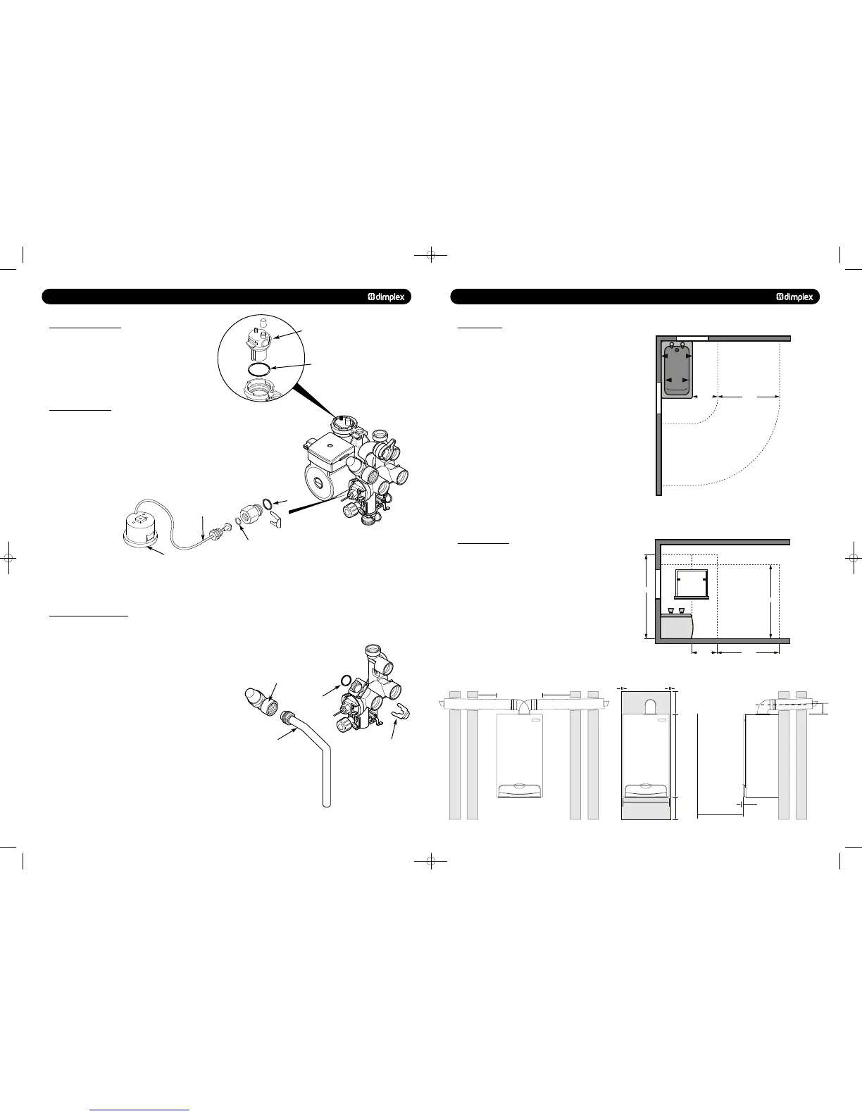
13.12 AUTOMATIC AIR VENT
1. Drain the primary circuit and rotate the automatic air vent
1
/
4
turn and remove from the pump body.
2. Examine the ‘O’ ring seal, replacing if necessary, and fit it to
the new automatic air vent.
3. Reassemble in reverse order.
1. Drain the primary circuit and undo the nut on the pressure
gauge capillary.
2. Examine the ‘O’ ring seal, replace if necessary.
3. Unclip the facia from the control box
4. Lever the barbs securing the gauge to remove the gauge
from the control box (Fig. 64).
5. Reassemble in reverse order.
13.14 PRESSURE RELIEF VALVE
1. Drain the primary circuit.
2. Disconnect the discharge pipe from the valve. Ease off the
retaining clip (Fig. 66).
3. Note the orientation of the valve, rotate it and withdraw it
from the manifold.
4. Fit the new valve and ‘O’ ring and set to the previously
noted orientation. Reassemble in reverse order.
Automatic Air Vent
‘O’ Ring
Pressure Gauge
Pressure
Relief Valve
Retaining Clip
‘O’ Ring
Discharge Pipe
Capillary
‘O’ Ring
‘O’ Ring
7.0 SITE REQUIREMENTS
7.1 LOCATION
1. The boiler may be fitted to any suitable wall with the flue
passing through an outside wall or roof and discharging to
atmosphere in a position permitting satisfactory removal of
combustion products and providing an adequate air supply. The
boiler should be fitted within the building unless otherwise
protected by a suitable enclosure i.e. garage or outhouse. (The
boiler may be fitted inside an unvented cupboard - see section
7.3).
2. If the boiler is fitted in a room containing a bath or shower
reference must be made to the relevant requirements.
In GB this is the current I.E.E. Wiring Regulations and Building
Regulations.
In IE reference should be made to the current edition of I.S.
813 “Domestic Gas Installations” and current ETCI rules.
(Fig. 11 shows zone dimensions for a bathtub. For other
examples refer to Section 601 of the current I.E.E. Wiring
Regulations) reference must be made to the relevant
requirements.
The boiler is IPX4 rated and can be fitted in Zone 2 (Fig. 11).
3. If the boiler is to be fitted into a building of timber frame
construction then reference must be made to the current
edition of Institute of Gas Engineers Publication IGE/UP/7 (Gas
Installations in Timber Framed Housing).
© Dimplex Boilers 2008
1. A flat vertical area is required for the installation of the
boiler.
2. These dimensions include the necessary clearance around
the boiler for case removal, spanner access and air movement.
Additional clearances may be required for the passage of pipes
around local obstructions such as joists running parallel to the
front face of the boiler.
Zone 2
Zone 2
Zone 1
Zone 0
Zone 3
Zone 3
Window Recess
Zone 2
Window
Recess
Zone 2
0.6 m 2.4 m
Zone 2 Zone 3
Zone 2Zone 1
Zone 0
Zone 3
Outside Zones
Ceiling
Window
Recess
Zone 2
3.0 m
2.25 m
0.6 m 2.4 m
285mm Wall
450mm Min
For Servicing
Purposes
5mm Min
In Operation
2.5°
5mm Min
446mm
5mm Min
796mm
200mm
200mm
5mm Min
5mm Min
285mm Wall
285mm Wall
751262 MANUAL 19/10/10 08:41 Page 13