7.0 SITE REQUIREMENTS
7.3 VENTILATION OF COMPARTMENTS
1. Where the appliance is installed in a cupboard or
compartment, no air vents are required.
Where an open flued system is used - Flue kit E (B23
classification) then an air vent communicating directly with
outside air must be provided in the same room or internal
space of the flue duct air inlet. Minimum free area:
System 18 = 88cm
2
System 30 = 159cm
2
In addition if an open flued system is used - Flue kit (B23
classification) and the boiler is fitted in a compartment, then
high and low level ventilation is required.
BS 5440-2:2000 gives guidance on compartmental ventilation.
2. When the boiler is installed in a cupboard or compartment
and either flue kit A, B, C, D or F (Classification C13, C33, C53)
is used, then no compartmental ventilation is required.
1. The gas installation should be in accordance with the
relevant standards. In GB this is BS 6891. In IE this is the
current edition of I.S. 813 “Domestic Gas Installations”.
2. The connection to the appliance is a 22mm copper tail
located at the rear of the gas service cock (Fig. 13).
3. Ensure that the pipework from the meter to the appliance is
of adequate size, and the demands of any other gas appliance
in the property are taken into consideration. Do not use pipes
of a smaller diameter than the boiler gas connection (22mm).
4. For boilers connected to use LPG (propane), the inlet
pressure must be 37mbar.
The completed installation should always be tested
for gas tightness
1. External wiring must be correctly earthed, polarised and in
accordance with relevant regulations/rules. In GB this is the
current I.E.E. Wiring Regulations. In IE reference should be
made to the current edition of the ETGI rules.
2. The mains supply is 230V - 50H
z
fused at 3A
The mains supply connection must allow complete
electrical isolation of the appliance and system controls
only.
Connection may be via a fused double-pole isolator with a
contact separation of at least 3mm in all poles and servicing
the boiler and system controls only.
Any additional mains cable should comply fully with the
current I.E.E. wiring regulations.
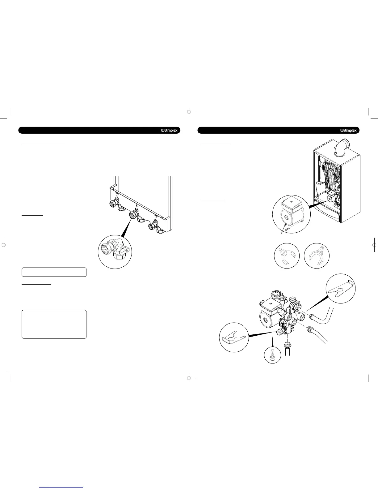
13.0 CHANGING COMPONENTS
13.10 PUMP - HEAD ONLY
1. Drain the primary circuit and disconnect the wiring
connector from the pump head.
2. Remove the four socket head screws securing the pump
head to the body and draw the head away (Fig. 62).
3. A replacement Grundfos 15-60 head can now be fitted
(Fig. 62)(Part No: 500672).
4. Reassemble in reverse order.
5. Replace the wiring connector into the socket on the pump
head.
© Dimplex Boilers 2008
1. Drain the primary circuit.
2. Remove the stainless clip at the base of the hydro-block and
disconnect the pipe (Fig. 63).
3. Un-lock the locking clip on the return port.
4. Disconnect the discharge pipe from the pressure relief valve.
5. Remove the two securing screws from below the boiler.
6. Carefully remove the hydro-block and change the relevant
components.
7. Reassemble in reverse order taking care to replace all the
clips correctly. Ensure the locking clip is in the ‘Locked’
position as shown opposite.
Pump Head
Front
Stainless Clip
Rear
Stainless Clip
Un-Locked
(viewed from pipe end)
Locked
(viewed from pipe end)
751262 MANUAL 19/10/10 08:41 Page 14