10.0 COMMISSIONING
10.2 FACTORY SETTINGS
1. With the boiler firing at maximum gas rate, check that the
inlet pressure at the appliance is 19mbar +/- 1mbar when
measured at the inlet pressure test point (Fig. 44).
To set the boiler to maximum gas rate see section
11.0 (Service Mode).
2. Check the maximum and minimum gas rate at the gas meter
according to the table below using a stopwatch.
This boiler is supplied factory set for operation on
natural gas. No further adjustments of the air/gas ratio
valve or measurement of the combustion performance are
necessary at the time of installation and commissioning.
This is provided the appliance has been installed according
to these instructions and the inlet gas pressure is within
our specification.
If any doubts exist over the above checks then the
combustion of the appliance can be measured as described
in Section 12.0 of these instructions providing;
• The person carrying out the measurement has been
assessed as competent in the use of a flue gas analyser
and the interpretation of the results.
• The flue gas analyser used, meets the requirements of
BS7927 or BS-EN50379-3.
• The flue gas analyser is calibrated in accordance with the
manufacturers requirements.
10.3 INLET PRESSURE AND GAS RATE CHECKS
1. On completion of the gas inlet pressure and gas rate checks,
it is necessary to check the following:
• The appliance installation conforms to these instructions.
• The installation and integrity of the full flue system
including the seals in the flue pipes.
• The boiler combustion circuit, including the burner door
seal, combustion door seal.
2. The recorded combustion values should be compared with
the values in Table 1 and Table 2 (see Section 12.2).
3. If the combustion value(s) is outside the values specified in
Section 12.2 (Tables 1 & 2), do not attempt to adjust the
air/gas ratio valve, please ring the helpline number -
0844 371 1121. If in doubt - ASK.
10.4 COMBUSTION CHECKS DURING COMMISSIONING
Gas Rates (Natural Gas) after 5 minutes from cold
Maximum RateBoiler Model
Factory set - warranty
void if adjusted
Throttle Adjuster Screw
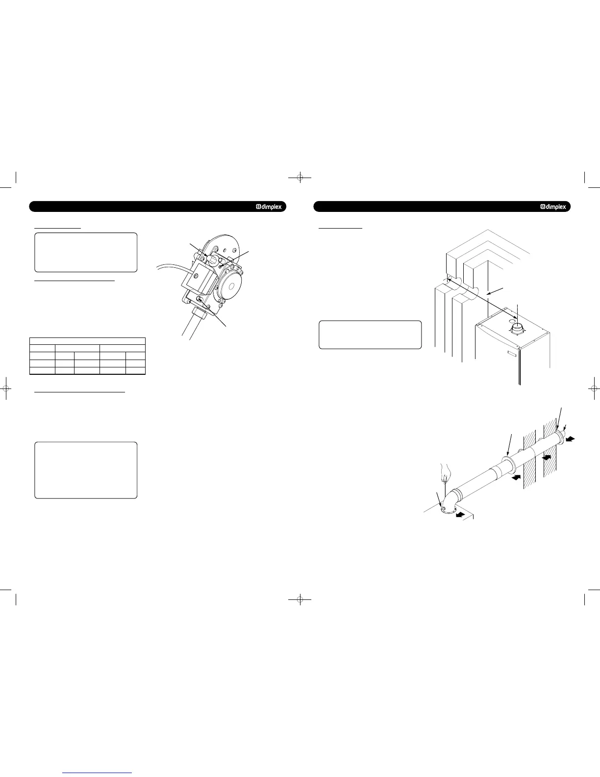
9.0 INSTALLATION
9.5 FITTING THE FLUE
HORIZONTAL TELESCOPIC FLUE
1. For correct flue installation please refer to the installation
instructions that are provided with the individual flue kit as
described in sections 7 & 8.
2. Measure the required flue length as shown in Fig. 34. Refer
to section 8 to determine whether any extension kits are
required. Installations using only the standard ducts or
standard ducts with straight extensions are described in this
section. Installation instructions for all other flue systems are
included in the various flue kits.
3. Ensure that all (inner and outer tube) sealing rings are
provided and assemble the air/flue ducts as shown in the flue
instructions.
4. Ensure that the flue and air seals are correctly fitted before
assembly and that each section is fully engaged.
NOTE: NEVER CUT THE SWAGED END. Where necessary the
plain ends of the extension ducts may be cut. Always
ensure that the cut is square and free of burrs or debris.
It is essential that the terminal is fitted the correct way up.
See flue kit instructions (i.e. rain shield at the top).
INSTALLING THE AIR/FLUE DUCT FROM INSIDE TH
Detailed installation instructions are included in the flue kit.
(Flue hole diameter 130mm).
1. Push the terminal through the wall taking care to ensure
that the terminal is the correct way round and the external
wall-sealing ring does not become dislodged.
2. Assemble the flue system extension ducts as necessary,
referring to Fig. 35.
3. Pull the flue system towards the appliance to seat the
external sealing ring against the outside wall, ensuring that the
duct joints are not disturbed.
4. Use the internal sealing ring to make good the internal hole
and check that the terminal is correctly located on the outside
wall. Where possible this should be visually checked from
outside the building (Fig. 35).
5. Finally locate and secure the elbow to the appliance using
the four screws provided.
INSTALLING THE AIR/FLUE DUCT FROM OUTSIDE THE BUILDING
Detailed installation instructions are included in the flue kit.
Flue hole diameter 100mm - 110mm.
1. Secure the flue elbow with seal to the appliance using 4
screws.
2. Fit the external wall sealing ring over the flue and then from
outside the building, push the flue system through the wall
taking care to ensure that the terminal is the correct way
around.
3. Loosely fit the internal wall sealing ring over the inside end
of the flue.
4. Assemble the flue system extension ducts as necessary
referring to the flue kit instructions and fit to the elbow.
5. Fit the flue terminal to the flue system, ensuring that the
duct joints are not disturbed and that the external sealing ring
is seated against the outside wall.
6. Finally use the internal sealing ring to make good the
internal hole. Check that the external wall sealing ring and the
terminal is correctly located on the outside wall.
© Dimplex Boilers 2008
‘L’ = Total flue length from flue outlet
centre to outside wall face
Align the assembled
flue system elbow to
appliance and secure
Slide internal wall
sealing ring to wall to
form a good seal
Insert assembled flue
system from inside the
room. External wall
sealing ring opens
External Wall
Sealing Ring
Terminal
To p
Internal Wall
Sealing Ring
751262 MANUAL 19/10/10 08:41 Page 23
 Loading...

