9.0 INSTALLATION
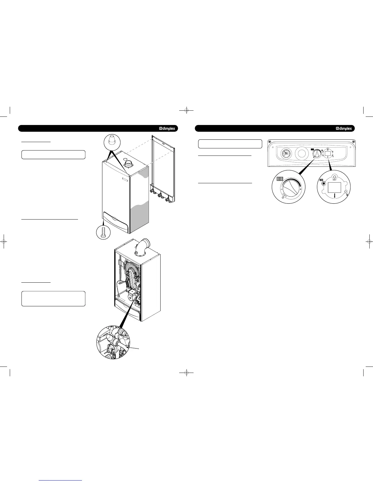
9.2 FITTING THE BOILER
1. Remove the sealing caps from the boiler connections.
NOTE: A small amount of water may drain from the boiler
once the caps are removed.
2. Check the sealing washers are located correctly in the taps
on the wall jig.
3. Lift the boiler as indicated by the shaded areas. The boiler
should be lifted by TWO PEOPLE. Engage the slots at the top
rear of the boiler on the wall plate (Fig. 31) (see
page 6).
4. Ensure the boiler is correctly located on the wall jig and the
connections align. Tighten all the connections.
9.3 FITTING THE PRESSURE RELIEF DISCHARGE PIPE
1. Remove the two screws securing the front panel to the
underside of the boiler. Rotate the bottom of the panel out
slightly and lift the panel upwards off its retaining studs on top
of the appliance.
2. Determine the route of the discharge pipe.
3. Taking care not to disturb the case sealing grommet, the
pipework must be at least 15mm diameter and run
continuously downwards to a discharge point outside the
building.
4. Complete the discharge pipework and route it to the outside
discharge point.
1. Connect the condensate drain to the trap outlet pipe.
Ensure the discharge of condensate complies with any
national or local regulations in force (see British Gas
“Guidance Notes for the Installation of Domestic Gas
Condensing Boilers”).
2. The connection will accept 21.5 - 22mm plastic overflow
pipe which should generally discharge internally into the
household drainage system. If this is not possible, discharge
into an outside drain is acceptable.
Pressure Relief
Discharge Pipe
Front Panel
Retaining Stud
Service Mode automatically stops after 10 minutes
and the boiler returns to normal operation.
1. Turn the CH knob fully clockwise - Note the knob will turn
past the maximum temperature mark (Fig. 45).
2. The CH light will flash continuously - the boiler is now
running at minimum rate.
1. Set the boiler into Service Mode at Minimum Rate.
2. Whilst in Service Mode at Min Rate, turn the CH knob to 12
‘O’ clock position and then back to fully clockwise (past the
maximum temperature indicator) within 3 seconds. The boiler
will now run at maximum gas rate for 10 minutes.
3. To exit Service Mode, turn the CH knob anti-clockwise to
the temperature previously set by the customer. The CH light
will now stop flashing.
11.1 TO SET THE BOILER AT MINIMUM GAS RATE
11.2 TO SET THE BOILER AT MAXIMUM GAS RATE
Fig. 45 Fig. 46
0
1
2
bar
3
4
751262 MANUAL 19/10/10 08:41 Page 22