12.0 SERVICING AND MAINTENANCE
12.1 ROUTINE SERVICING AND ALL MAINTENANCE THAT
INVOLVES THE EXCHANGE OF PART OF THE
COMBUSTION CIRC
1. During routine servicing, e.g. an annual service check, and
after all maintenance that involves the exchange of parts of
the combustion circuit, we recommend that (in this order) the
integrity of the full flue system and combustion circuit seals,
the inlet gas pressure, gas rate and combustion performance is
verified.
The combustion circuit on this appliance comprises
of the PCB, fan, air/gas ratio valve, burner, burner door,
combustion box door, injector and flue system.
2. To ensure continued safe and efficient operation of the
appliance it is recommended that the boiler is serviced at least
annually. Servicing must be performed by a competent person.
BS 7967-1 gives guidance on identifying and managing
sources of fumes, smells, spillage/leakage of combustion
products and carbon monoxide detector activation.
On any service visit always check;
a. Condition of flue system, both air and combustion products
ducts.
b. Condition of seals and joints.
c. For evidence of leakage of combustion products.
d. For evidence of heat staining.
e. For operation at maximum heat input.
f. The general condition of the boiler and its components.
1. Combustion checks must be carried out with the outercase
fitted.
2. Remove the sampling cap from the boiler flue elbow or
boiler vertical flue adaptor.
3. Insert the probe from the portable electronic combustion
analyser into the sampling point.
4. With the appliance operational, connect the flue gas
analyser to the flue sampling point as shown in Fig. 47.
The outercase must be fitted for all combustion
checks.
5. With the boiler at minimum rate and then at maximum rate
(allowing the combustion to stabilise at each rate before taking
a reading) carry out the combustion checks as follows:
COMBUSTION CHECKS AT MINIMUM RATE
6. The combustion values at minimum gas rate and maximum
gas rate must be checked using a suitable calibrated flue gas
analyser. Further guidance is detailed in BS7967 parts 1 to 4.
7. Set the boiler into Service Mode at Min Rate
(see section 11.1).
8. Check the Carbon Monoxide (CO) and Carbon Dioxide (CO
2
)
readings are within the range quoted in the tables opposite
(Table 1).
Carbon
Monoxide
CO
p.p.m
0 - 40
0 - 40
Carbon
Dioxide
CO
2
%
8.5 - 8.9
8.7 - 9.1
Carbon
Monoxide
CO
p.p.m
80 - 160
80 - 160
Carbon
Dioxide
CO
2
%
10.4 - 10.8
10.3 - 10.7
Carbon
Monoxide
CO
p.p.m
15 - 60
15 - 60
Carbon
Dioxide
CO
2
%
8.8 - 9.2
8.8 - 9.2
Carbon
Monoxide
CO
p.p.m
80 - 160
80 - 160
Carbon
Dioxide
CO
2
%
10.8 - 11.2
10.5 - 10.9
9.0 INSTALLATION
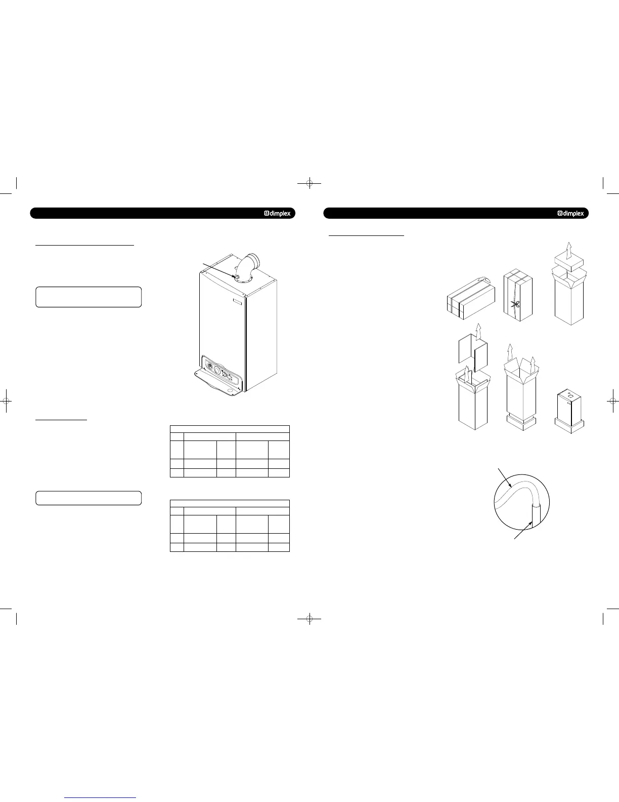
9.1 UNPACKING & INITIAL PREPARATION
The gas supply, gas type and pressure must be checked for
suitabi
1. Remove the top cardboard tray from the carton.
2. The wall fixing jig is packed in its own cardboard sleeve.
Carefully slide this out of the carton.
3. To avoid scratching the boiler outercase, keep the outer
carton in place.
4. After reviewing the site requirements (see Section 7.0),
position the fixing template on the wall ensuring it is level both
horizontally and vertically.
5. Mark the position of the fixing holes for the wall plate and
boiler lower fixing holes.
6. Mark the position of the centre of the flue hole (rear exit).
For side flue exit, mark as shown (Fig. 4).
7. If required, mark the position of the gas and water pipes.
Remove the template.
8. Cut the hole for the flue (minimum diameter 110mm).
9. Drill the wall as previously marked to accept the wall plugs
supplied. Secure the wall fixing jig using the fixing screws.
10. Using a spirit level ensure that the fixing jig is level before
finally tightening the screws.
11. Flush and clean the system using an appropriate cleanser
(Fig. 30).
12. Connect the gas and water pipes to the valves on the wall
fixing jig.
13. Fit the filling loop as described in the instructions supplied
with it.
© Dimplex Boilers 2008
Flushing Pipe
Central Heating Flow
or Return Pipe
751262 MANUAL 19/10/10 08:41 Page 21
 Loading...

