8.0 FLUE OPTIONS
8.10 FLUE LENGTHS
Length supplied in standard kit - horizontal 815mm
Max horizontal length (from boiler to chimney - 60/100mm) 2000mm
Min horizontal length (from boiler to chimney - 60/100mm) 100mm
Max vertical length (from boiler to chimney - 60/100mm) 2000mm
Min vertical length (from boiler to chimney - 60/100mm) 200mm
Length supplied in standard kit - vertical (available in 10m, 20m an 30m length) N/A
Flexitube must be purchased as an accessory to complete the kit (see below)
Flexitube min length 5m
Flexitube max length 30m
Description Part No. Equivalent Length
Horizontal - 60/100 Accessories
Flue extension duct - 500mm 956092 450mm
Flue extension duct - 1000mm (incl. 1 x support bracket) 956093 950mm
93° extension elbow 956091 1550mm
45° extension elbow (pair) 956090 775mm
Air inlet duct - included in kit N/A N/A
Straight adaptor (60/80) - included in kit N/A N/A
91.5° adaptor elbow (80/80) - included in kit N/A N/A
Support bracket - 100mm 840517 N/A
93° flanged elbow - included in kit 956082 N/A
Vertical turret socket 956087 N/A
Flexi tube - 10m 956110 10m
Flexi tube - 20m 956111 20m
Flexi tube - 30m 956112 30m
Straight duct (80) - included in kit N/A N/A
Chimney terminal - included in kit N/A N/A
Note: Equivalent length information only required for coaxial flue parts.
The corrugated (Flexi tu
be) flue parts are fixed and all parts are required for every application.
20
8.11 Additional Concentric Flue Kit Accessories
The following additional concentric kit accessories are available
as optional extras.
Flue Extension Ducts - 1000 mm (956093) and 500 mm
(956092), (each duct extends the flue length by up to 950
mm and 450 mm respectively).
93° Extension Elbow (956091) - Allows an additional bend in
the flue, and has an ‘equivalent length’ of 1550 mm. This
elbow is mechanically different from the flanged elbow
supplied as standard with the appliance, but has the same
equivalent length.
45° Extension Elbow (956090) - Allows an additional bend in
the flue and has an ‘equivalent length’ of 775 mm.
Vertical Turret Socket (956087) - For use with elevated
horizontal flues and vertical terminals.
Vertical Roof Terminal - For use where an external wall is not
available, or where it is desirable to route the ducts vertically.
For installation details refer to the instructions provided with
the individual flue kits.
These optional kits may be used with the standard flue kits to
produce an extensive range of flue options, providing that the
following rules are strictly obeyed.
a) The maximum/minimum permissible length of the room
sealed flue system are:
Horizontal flue terminal (all orientations)
maximum 10000 mm
Horizontal flue terminal (rear exit)
minimum 250 mm
Vertical flue terminal maximum 12000 mm
Vertical flue terminal minimum 600 mm
The ‘equivalent’ flue length must not exceed the maximum
values stated.
b) The standard terminal must be fitted horizontally; horizontal
ducts must have a continuous fall towards the appliance of
1.5° to 3°. This ensures condensate runs back into the
appliance from the flue system. The vertical terminal must
always be used if a vertical outlet is required.
c) The concentric flue system must use either a flanged elbow
or a vertical flue turret socket at the entry/exit to the
appliance.
d) All joints must be correctly made and secured in accordance
with the installation instructions. When cutting ducts, avoid
swarf, uneven and sharp edges to maintain duct integrity.
Refer to Fig. 19 & 20 to determine which option kits are
required before commencing the installation. Instructions for
installing the appliance with a horizontal flue and straight
extension ducts are included in the main text of these
instructions (section 9.5).
12.0 SERVICING AND MAINTENANCE
12.2 COMBUSTION CHECKS
COMBUSTION CHECKS AT MAXIMUM RATE
9. Set the boiler to Maximum gas rate.
10. Check the Carbon Monoxide (CO) and Carbon Dioxide (CO
2
)
readings are within the range quoted in the tables opposite
(Table 2).
11. If the combustion value(s) is outside the values specified
in Tables 1 and 2 and the integrity of the full flue system and
combustion circuit seals, the inlet gas pressure and gas rate
have been verified, it is possible to make an adjustment to the
combustion settings by adjustment of the air/gas ratio valve.
See Section 12.3 Adjustment of the Gas Valve.
© Dimplex Boilers 2008
29
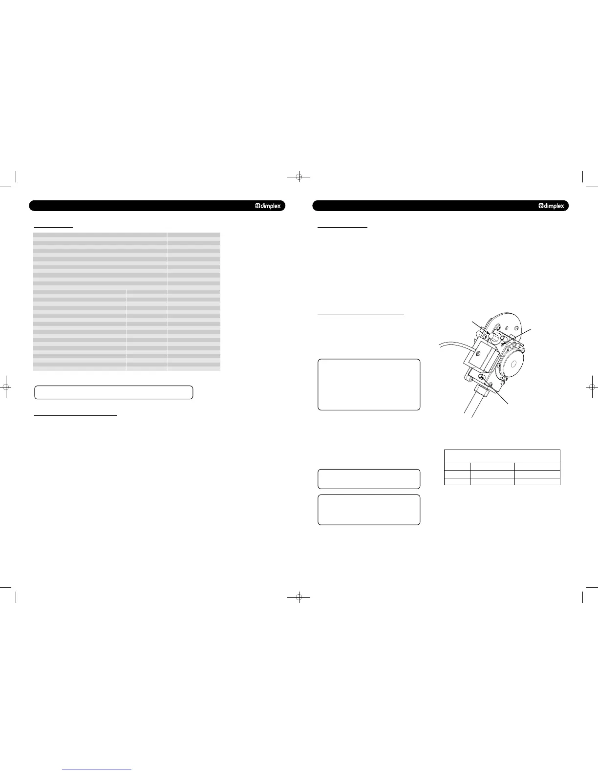
12.3 ADJUSTMENT OF THE GAS/AIR RATIO VALVE
COMBUSTION SETTING ADJUSTMENT
1. It is only possible to adjust the valve at Maximum rate. No
adjustment at Minimum rate is allowed.
2. If the maximum rate setting is adjusted, then the
combustion values must be checked at minimum rate.
DO NOT ATTEMPT TO ADJUST THE GAS/AIR RATIO
VALVE UN LE S S ;
• The person carrying out the measurement has been
assessed as competent in the use of a flue gas analyser
and the interpretation of the results.
• The flue gas analyser used, meets the requirements of
BS7927 or BS-EN50379-3.
• The flue gas analyser is calibrated in accordance with the
manufacturers requirements.
3. At Maximum Gas Rate; put the appliance into Service Mode
at Maximum Gas Rate (see Section 11.2).
4. Wait 5 minutes to allow the boiler to stabilise.
5. If the Carbon Dioxide (CO
2
) level is outside the required
values given in Section 12.2 (Table 2) then adjust the throttle
screw (Fig. 48) until the CO
2
is at the correct setting level. See
Table 4. Clockwise to decrease CO
2
, anti-clockwise to increase
CO
2
.
Only turn the throttle in small steps of
no more than
1/8
th
of a turn
and wait 1 minute after each adjustment for
the combustion reading to stabilise.
After any adjustment of the gas valve, it is
essential to check the combustion levels at minimum gas
rate (Table 1). If the Carbon Monoxide or Carbon Dioxide
levels are outside the range quoted, call Dimplex Boilers Ltd
Technical Helpline on 0844 3711121. If in doubt ASK!
Factory set - warranty
void if adjusted
Throttle Adjuster Screw
Carbon Dioxide (CO2) acceptable setting level at Maximum
Gas Rate after 5 minutes operation
Natura
l Gas %Boiler Model
System 18
751262 MANUAL 19/10/10 08:41 Page 20
 Loading...

