12.0 SERVICING AND MAINTENANCE
12.1 ANNUAL SERVICING
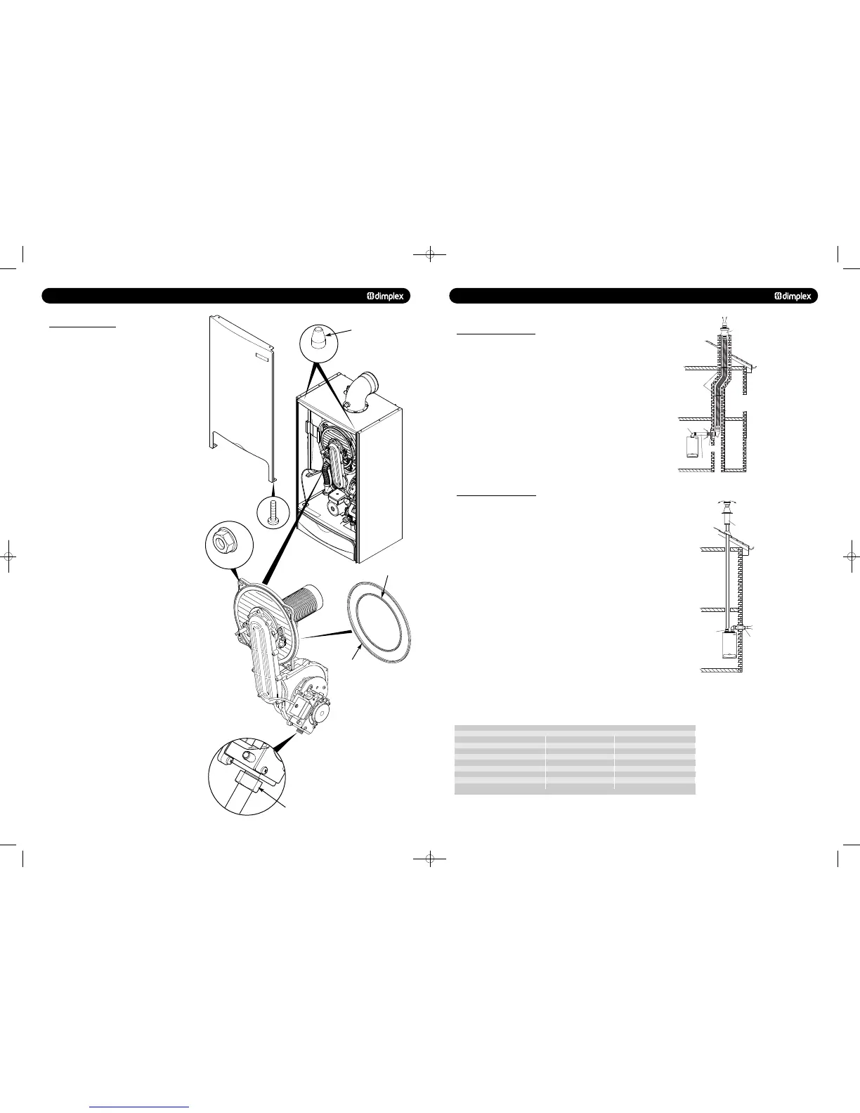
8. Remove the two screws securing the front panel to the
underside of the boiler. Lift the panel upwards off its retaining
studs on top of the appliance.
9. Disconnect the two leads to the fan and one lead to the gas
valve.
10. Undo the nut on the gas inlet pipe to the valve and retain
the sealing washer.
11. Remove the four nuts holding the burner door plate and
remove the valve and fan assembly (Fig. 51).
12. Clean any debris from the heat exchanger using a soft
brush and check that the gaps between the tubes are clear.
13. Inspect the burner, electrode positions and insulation,
cleaning or replacing if necessary.
14. Check the condition of the burner door seals, replacing if
necessary.
15. Reassemble in reverse order.
16. Complete the relevant Service Interval Record section of
the Benchmark Commissioning Checklist at the rear of this
publication and then hand it back to the user.
Fig. 51
Fig. 49
Fig. 50
Fig. 52
Gas Inlet Nut
Front Panel
Retaining Stud
Burner Door Seal
Inner Seal
8.0 FLUE OPTIONS
8.8 Kit E Chimney Flue Liner Kit
(B23) - Part no. 956082
This kit is suitable for open flue application in accordance with
BS5440 where a room sealed flue installation is impractical.
The kit comprises of a flue adaptor from the appliance to the
chimney, a flexible plastic flue liner with connection parts and
chimney terminal (see Fig. 27). Where an open flue system is
used, then an air vent must be provided in the same room or
internal space as the flue duct air inlet, see section 7.3.
For installation details refer to the flue kit instructions.
Maximum flue resistive length = 30m.
A flue system can be built up from the components detailed in
table 8.10, but the total flue resistance must not exceed the
maximum stated.
© Dimplex Boilers 2008
19
8.9 Kit F: Twin Flue System
(C53) - Part no. 956080
This flue system kit is designed for installations where the air
intake position is different than the flue duct exit point. The kit
comprises of a twin adaptor from which the air intake is taken
from the adjacent outside wall (see Fig. 28) and the flue duct
is routed vertically through the roof.
It has to be noted that the flue duct is under pressure when
the appliance is in operation and the duct can leak poisonous
carbon monoxide if the duct components are not correctly
assembled. It is
recommended to route the flue duct
through living space areas, i.e. bedrooms, living rooms etc.
For installation details refer to the instructions provided with
the twin flued kit.
For C53 flue systems the terminal for the supply of
combustion air and for the evacuation of combustion products
shall not be installed on opposite walls of the building.
Maximum flue resistance permitted for a twin flued system
= 52 Pa
Minimum flue resistance permitted for a twin flued system
= 23.5 Pa
Centralising brackets
Chimney terminal
93 flanged elbow (concentric)
with sampling point
Ø60/100mm concentric
chimney adaptor pipe.
In replacement installations,
the chimney has to be
cleared of debris and
all flue parts.
Chimney
plate
Flexible corrugated plastic flue liner
Ø80mm according to EN 14471
Max. length 30m.
Min. length 5m.
KIT E
Chimney flue liner kit - Part no. 956082
Flue Component Flue Resistance (Pa) Part Number
Twin Flue Adaptor (required) 9.5 -
Air Inlet Terminal (required) 3 -
Chimney Terminal (required) 0.5 -
80 mm dia straight duct 1 metre 1 956101
80 mm dia straight duct 2 metre 2 956102
90° Elbow (80/80) 8 956100
45° Elbow (80/80) 4 956099
A flue system can be built up from the components detailed in the table, but the total flue
resistance must not exceed the maximum stated.
Ø80mm air intake
Split flue system
Roof terminal with pitched
roof flashing kit.
If the flue pipe passes
through compartment
from wall/floors, the
requirements set out
in Building Regulations
Part B must be followe
d.
Ø80mm twin adaptor
with sampling point.
If the flue pipe passes
through habitable rooms
within the same dwelling,
the flue pipe must be
routed through vented
ducts.
The flue resistance for the
following accessories has
to be considered.
Ø80mm flue extension
90 elbow
45 elbow
Split pipe vertical
flue outlet kit -
Part no. 956080
Kit F
!
751262 MANUAL 19/10/10 08:41 Page 19
 Loading...

