13.0 CHANGING COMPONENTS
13.6 FLUE/HEAT TEMPERATURE THERMOSTAT
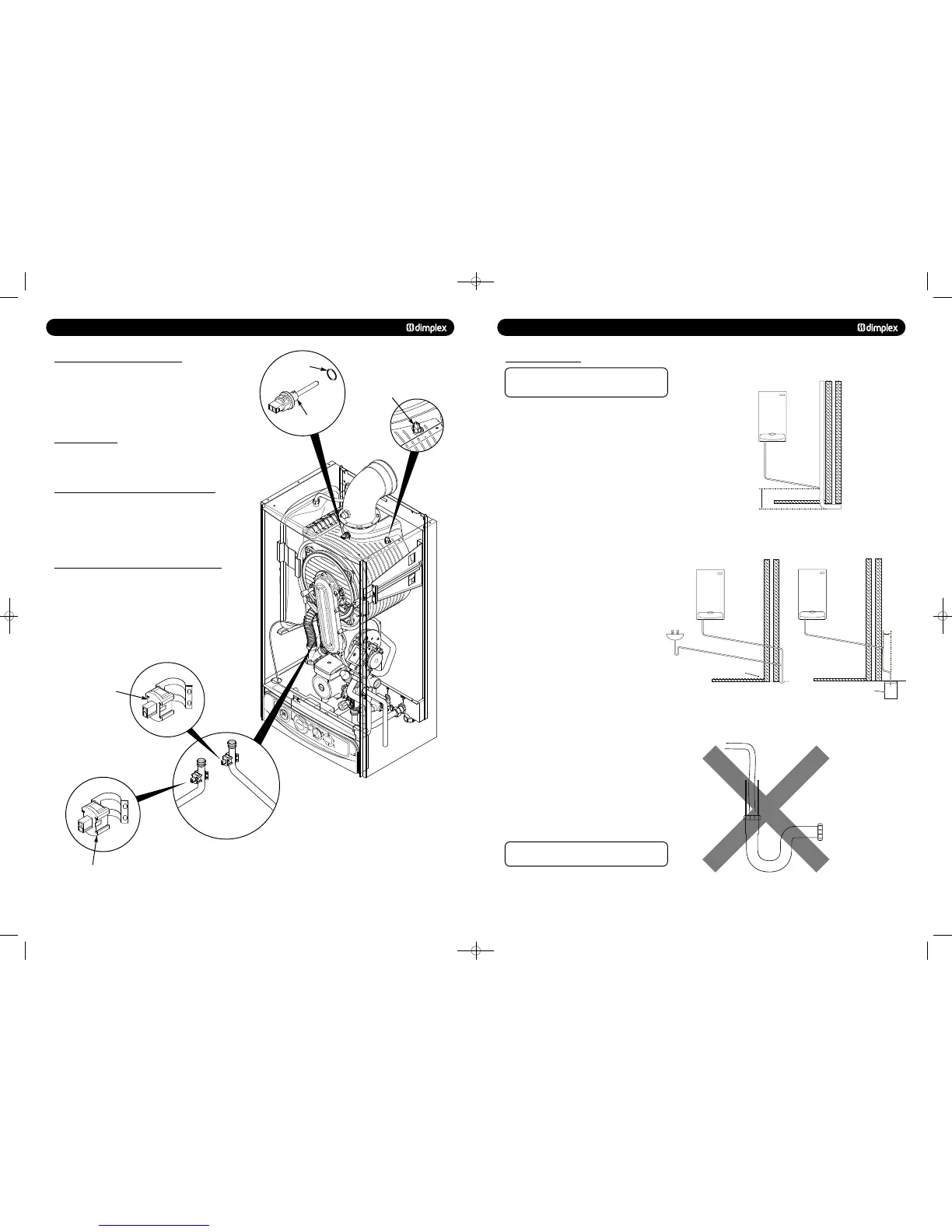
1. Disconnect the electrical plug.
2. Turn the sensor 90° anticlockwise to remove - it is a
bayonet connection (Fig. 60).
3. Reassemble in reverse order.
1. The thermal fuse is non-changeable. If the fuse fails contact
Dimplex Technical Department.
13.8 CENTRAL HEATING FLOW TEMPERATURE THERMISTOR
1. Disconnect the electrical plug.
2. Ease the sensor clip away from the pipe and remove (Fig. 61).
3. Reassemble in reverse order.
13.9 CENTRAL HEATING RETURN TEMPERATURE THERMISTOR
1. Disconnect the electrical plug.
2. Ease the sensor clip away from the pipe and remove (Fig. 61).
3. Reassemble in reverse order.
0
1
2
b
ar
3
4
‘O’ Ring
Thermal Fuse
Central Heating Flow
Temperature Thermistor
Central Heating Return
Temperature Thermistor
Flue/Heat Temperature
Thermostat
7.0 SITE REQUIREMENTS
7.6 CONDENSATE DRAIN
NOTE:
The appliance is fitted with a trap the depth of
which is >= 75mm, therefore no other traps are required in
the condensate run.
The condensation discharge pipe must not rise at any point
along its length. There MUST be a fall of AT LEAST 2.5° (50mm
per metre) along the entire run.
1. The condensate outlet will accept 21.5mm (
3
/
4
in) plastic
overflow pipe which should discharge internally into the
household drainage system, downstream of all other traps. if
this is not possible, discharge into an outside drain is
acceptable.
2. Ensure the discharge of condensate complies with any
national or local regulations in force.
BS 6798:2000 & Part HI of the Building Regulations give
further guidance.
3. Metal pipework is NOT suitable for use in condensate
discharge systems.
4. The pipe should be a minimum of 21.5mm diameter and
must be supported properly.
5.
to keep the condensate pipe internal.
External runs greater than 3 metres or runs in cold areas
sho
7. If the boiler is fitted in an unheated location the entire
condensate discharge pipe should be treated as an external
run.
8. In all cases discharge pipe must be installed to aid disposal
of the condensate.
9. When discharging condensate into a soil stack or waste pipe
the effects of existing plumbing must be considered. If soil
pipes or waste pipes are subjected to internal pressure
fluctuations when WC’s are flushed or sinks emptied then
back-pressure may force water out of the boiler trap and
cause appliance lockout.
Examples are shown of the following methods of terminations
(see figs. 14,15 & 16):
i) to an internal soil & vent pipe
ii) via and internal discharge branch (e.g. sink waste)
iii) to a drain or gully
iv) to a purpose made soakaway
10. In exceptional circumstances, such as when a boiler is
installed in a basement without drainage, it may be necessary
to install a condensate pump to carry condensate up to ground/
drain level. Such products are available from most plumbing
merchants. For help with selecting a condensate pump contact
Dimplex Boilers - Tel: 0844 3711121.
There must be no air breaks in the condensate
pipework or drainage system (see Fig. 17).
© Dimplex Boilers 2008
50mm per metre of pipe run
2.5° Minimum fall
450mm min
Termination to an internal soil and vent pipe
50mm per metre of pipe run
2.5° Minimum fall
External termination via internal discharge branch
e.g sink waste - downstream
Sink
Pipe must terminate
above water level but
below surrounding surface.
50mm per metre of pipe r
un
2.5° Minimum fall
Termination to a purpose made soak-away
Holes in the soak-away must
face away from the building
500mm min
NOT ALLOWED
There should be
no air gap
Fig. 14
Fig. 15
Fig. 17
Fig. 16
751262 MANUAL 19/10/10 08:41 Page 15
 Loading...

