7.0 SITE REQUIREMENTS
7.7 FLUE
1. This high efficiency boiler will discharge a plume of water
vapour from the flue. This should be considered when siting
the flue terminal.
2. The following guidelines indicate the general requirements
for siting balanced flue terminals. For GB recommendations are
given in BS 5440 Pt 1. For IE recommendations are given in
the current edition of I.S. 813 “Domestic Gas Installations”.
3. If the terminal discharges onto a pathway or passageway,
check that combustion products will not cause a nuisance and
that the terminal will not obstruct the passageway.
4. If a terminal is less than 2 metres above a balcony,above
ground or above a flat roof to which people have access, then
a suitable terminal guard must be provided - Part No: 951507.
of the 25mm clearances (Positions ‘O’ to ‘S’ in
the chart below) is allowable per installation.
• Under car ports we recommend the use of the plume
displacement kit.
• The terminal position must ensure the safe and nuisance
- free dispersal of combustion products.
NOTE: The minimum distance from a flue terminal to a boundary line is 300mm.
If fitting a plume div
erter kit, the air inlet should be a minimum of 100mm from
any opening windows or doors.
NOTE A: A term
inal should
be no closer than 150mm
to an opening in the
brickwork intended to
accommodate a fitt
ing
such as a window frame.
NOTE: Fitting of the deflector
elbow is recommended when
installing boil
er to minimum
clearance of 25mm as
detailed in positions O & P.
A
M,L
M,L
N
C
F
P
O
O
R
N
S
C
C
N
Flue terminals that require a guard fitting
P
B
J
H
N
N
G
Q
K
D
E
Position Description Minimum Distance (mm)
A Horizontally to an opening, air brick, opening window - see note A 300
B Above an opening, air brick, opening window etc. - see note A 300
C Below an opening, air brick, opening window etc. - see note A 300
D Below windows or openings on pitched roofs 2000
E Adjacent to windows or openings on pitched and flat roofs 600
F From an adjacent opening window (vertical only) 1000
G From an adjacent wall to flue (vertical only) 300
H Horizontally from a terminal on the same wall 300
J Vertically from a terminal on the same wall 1500
K From an opening in a carport (e.g. door, window) into the dwelling 1200
L From a terminal facing a terminal (horizontal flue) 1200
From a terminal facing a terminal (vertical flue) 600
M From a surface or boundary line facing a terminal 600
N Above ground, roof or balcony level 300
O From an internal or external corner 25
P From a vertical drain pipe or soil pipe 25
Q Below balconies or car port roof 25
R Below eaves 25
S Below gutters, soil pipes or drain pipes 25
300mm Min 300mm Min
Adjoining Properties Boundary Line
TERMINAL POSITION
Fig. 18
Fig. 19
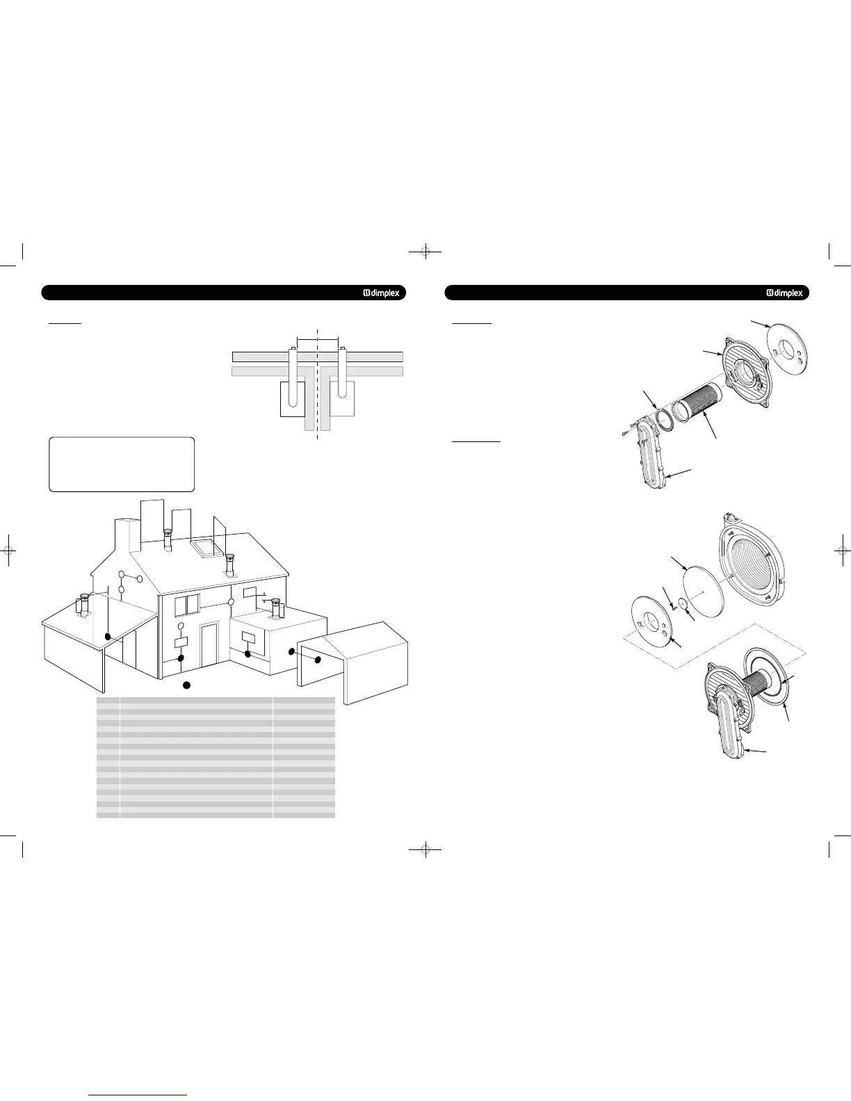
13.0 CHANGING COMPONENTS
13.4 BURNER
1. Remove the valve and fan assembly as described in Section
13.3.
2. Examine the gasket and replace if necessary.
3. Undo the four nuts securing the burner door and remove
from the heat exchanger.
4. Slowly withdraw the burner from the burner plate taking
care not to damage the insulation (Fig. 58).
5. Reassemble in reverse order.
© Dimplex Boilers 2008
1. Remove the electrode leads, noting their positions. Remove
the electrodes as described in section 13.2.
2. Remove the valve and fan assembly as described in Section
13.3.
3. Examine the gasket and replace if necessary.
4. Undo the four nuts securing the burner door and remove
from the heat exchanger.
5. Slowly withdraw the burner from the burner door.
6. Replace the insulation if necessary.
7. Check the burner door seals.
8. The rear insulation is retained by a screw and large washer,
remove these and draw the insulation out of the heat
exchanger (Fig. 59).
9. Reassemble in reverse order.
Burner
Insulation
Gasket
Air/Gas Channel
Rear Insulation
Washer
Insulation
Retaining Screw
Burner Assembly
Burner Door
Burner Door Seal
Inner Seal
751262 MANUAL 19/10/10 08:41 Page 16
 Loading...

