7
Electric Blower Heater
Assembly Instructions
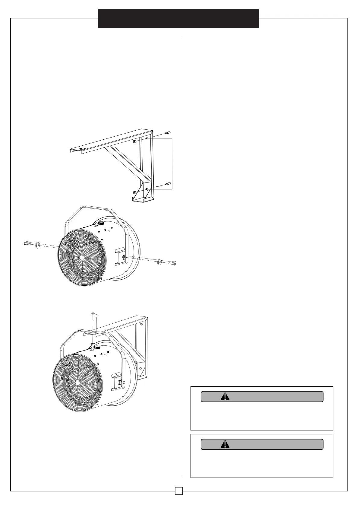
Wall Mount Installation Instructions:
1. Keep unit at least 8 feet (1.8 m) away from floor. Minimum
distance must be maintained.
2. Do not install closer than 1 foot (or 0.3 m) to any adjacent
vertical surfaces or walls.
3. Keep at least 4.5 inches (11.5 cm) from back wall (with or
without wall hanging mounting bracket).
4. Mark drill-hole positions in wall or ceiling for mounting
bracket.
5. Drill holes for required diameter fit (anchor provided) to
ensure correct position for mounting bracket.
6. Insert anchors.
8. Attach bracket to heater housing with hex bolts and
rubber pads. Insert lock pin.
7. Confirm mounting bracket is securely
attached to wall or ceiling with screws.
9. Mount heater assembly onto mounting bracket and
align holes. Insert hex bolt and tighten with nut.
Install lock pin.
10. Connect the electrical power supply cable in flexible
conduit to wiring compartment.
11. Attach with connectors suitable for conductor size
and ground wiring. After completing the connections,
arrange pigtail unit leads and power supply wires in
wiring compartment.
All servicing or maintenance should be performed by
qualified service personnel.
Prior to maintenance be sure to:
1. Disconnect power supply at source.
2. Wait 60 minutes to ensure heating element is cool.
Routine Maintenance:
1. Do not spray or use cleaning liquids or other chemicals
on unit.
2. Interior dust can often be removed with a vacuum
cleaner and crevice tool attachment.
3. To clean enclosure, use a clean, soft and lightly damp
cloth to gently wipe off dirt from surface. Be sure not
to wet heating element or switches. Allow unit to dry
completely before restarting.
MAINTENANCE AND CLEANING
CAUTION
WARNING
Do not allow water to run into the interior of the
heater as this could cause a fire, an electric shock
hazard and damage the unit.
This unit must only be used with the provided floor
stand or optional ceiling bracket. Heater must be
installed with the power switch at the top of the unit.
• Switch on the circuit breaker and On/Off rocker switch
to turn on heater. Turn thermostat to furthest clockwise
position. Fan will begin heating the room.
• Select a thermostat setting. Ambient temperature is
regulated by adjusting the thermostat to a desired
position. Allow unit to operate and warm the room.
Wh en de si re d te mp er at ure i s re ac he d, tu rn co nt rol kn ob
counterclockwise until heater turns off. The heater will
start automatically when the room temperature drops
below this set point and will turn off when set point is
reached. The fan will remain on.
• Adjust thermostat with each use.
• T o turn off heater, position the On/Off rocker switch
and circuit breaker to Off.
SAFETY TIP-OVER SWITCH
Models 653558, 653559, 653560 and 653561 are
designed to automatically shut off when heater is tipped
sideways. Place unit on level surface to prevent tipping.
•
Apply appropriate personal protective equipment
(PPE) and follow safe electrical work practices.
See NFPA 70
• Circuit breaker must be installed and serviced only
by qualified electrical personnel.
• Always use a properly rated voltage device to
confirm power is off.
• Confirm there are no materials near front or
rear grills.
OPERATING INSTRUCTIONS
HAZARD OF ELECTRIC SHOCK,
EXPLOSION OR ARC FLASH:
when heater is tipped sideways. Place unit on level
surface to prevent tipping.