8545-0198-01 Revision 1.9 STX3 Users Manual
9/24/2020 Globalstar, Inc. Confidential and Proprietary Page | 9
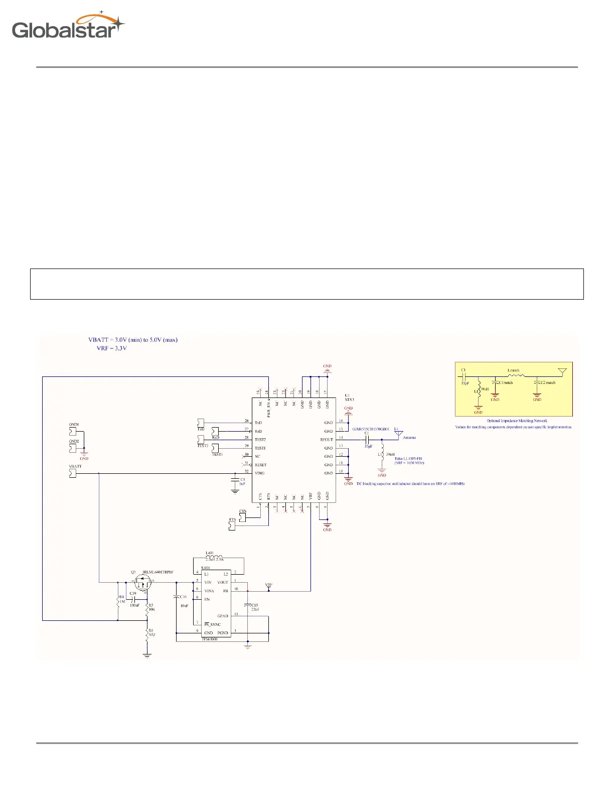
4 Reference Design
The following is a reference design which illustrates a typical implementation of a simplex transmitter device using the STX3 and a
commercially available antenna. OEM designs are required to follow these guidelines with respect to the antenna configuration and
layout. Physical layout, PCB size and stack-up, component part numbers, etc. may vary. However, the following conditions must be
met in order to comply with the STX3 modular grant.
1. The antenna used must be a patch antenna.
2. The antenna peak gain must not exceed 5.1 dB.
3. The antenna must be passively connected to the RF output of the STX3 using a 50-ohm nominal impedance printed circuit
trace. No connectors are allowed on the antenna connection.
If any of the above conditions are not met, the OEM device must be submitted for FCC Part 25 testing (and any additional
certification testing required in the intended geographical service area).
In addition, it is strongly recommended that the OEM design include ESD protection circuitry as specified below. The circuit below
provides a DC blocking capacitor as well as a shunt inductor to short any static discharge from the antenna to ground.
The values and part numbers below have been tested and provide ESD protection with minimal insertion loss.
Figure 7 Reference Design Schematic