16
4000123942-2
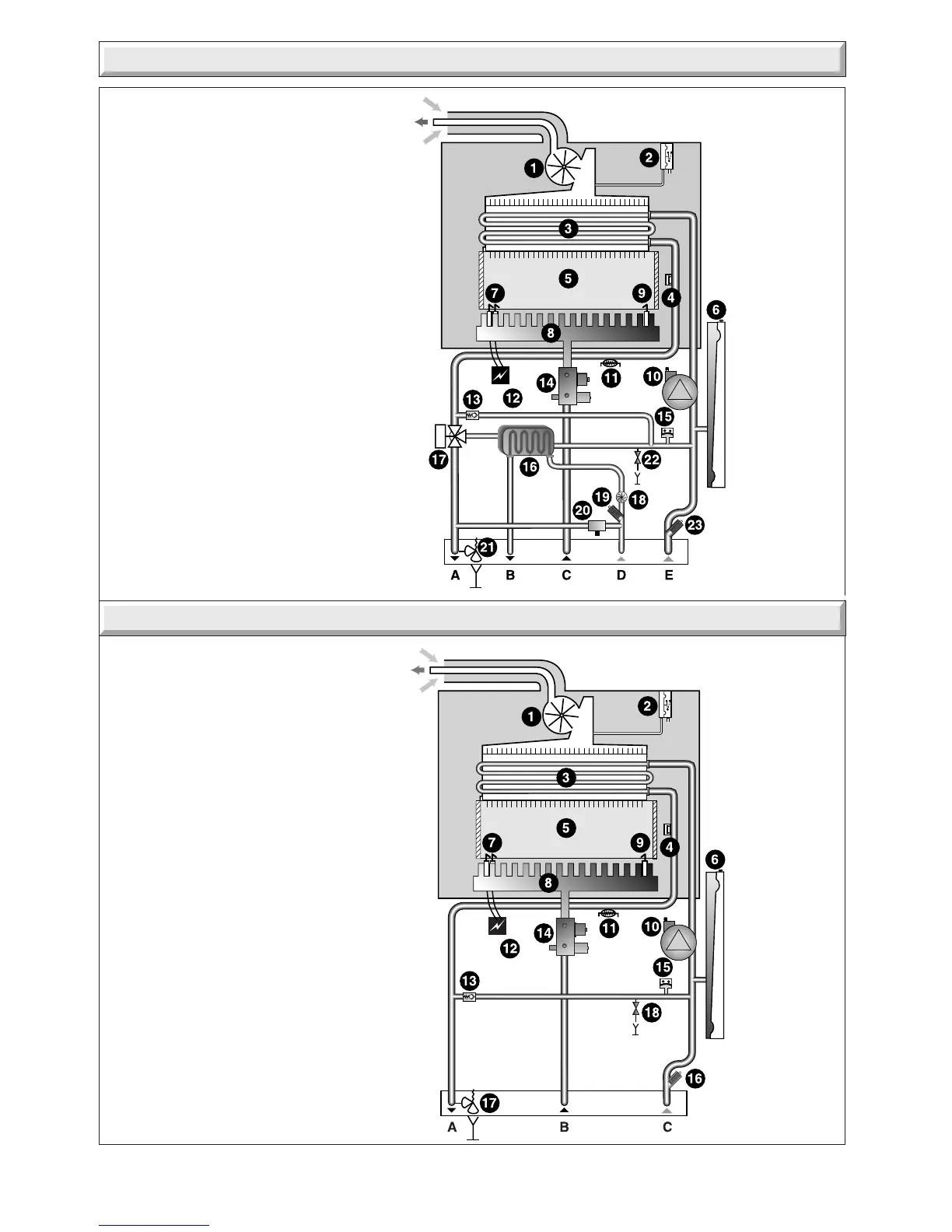
1 - Fan.
2 - Air pressure switch.
3 - Heat exchanger.
4 - Overheat thermostat.
5 - Combustion chamber.
6 - Expansion vessel.
7 - Ignition electrode.
8 - Burner.
9 - Flame sense electrode.
10 - Pump.
11 - Heating thermistor.
12 - Ignition unit.
13 - By-pass.
14 - Gas control valve.
15 - Loss of water sensor.
16 - Heating filter.
17 - Discharge safety valve (3bar).
18 - Drain valve
A - Heating flow.
B - Gas.
C - Heating return.
Diagram 5a.1
11450
FITTED TO
REAR OF
APPLIANCE
5a Boiler Schematic 18si
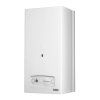
1 - Fan.
2 - Air pressure switch.
3 - Heat exchanger.
4 - Overheat thermostat.
5 - Combustion chamber.
6 - Expansion vessel.
7 - Ignition electrode.
8 - Burner.
9 - Flame sense electrode.
10 - Pump.
11 - Heating thermistor.
12 - Ignition unit.
13 - By-pass.
14 - Gas control valve.
15 - Loss of water sensor.
16 - Domestic heat exchanger
17 - 3 way valve
18 - Domestic water flow sensor
19 - Filter cold water inlet
20 - Filling system
21 - Discharge safety valve (3bar)
22 - Drain valve
23 - Heating filter
A - Heating flow
B - Domestic hot water outlet
C - Gas
D - Cold water inlet
E - Heating return
5 Boiler Schematic 24ci
9899
FITTED TO
REAR OF
APPLIANCE
Diagram 5.1
 Loading...


