27
10.7 Standard Horizontal Flue - A2043400
Refer to diagram 10.12 for kit contents.
10.8 REAR Flue
Remove the top ue outlet cover secured with four screws,
see diagram 10.4.
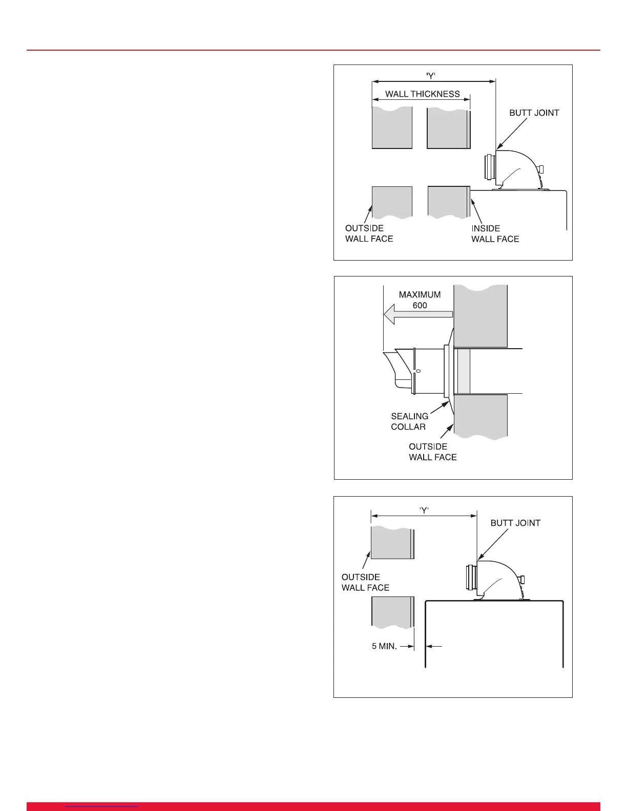
Using these screws inserted into the same holes on the boiler,
temporarily secure the ue elbow, measure the distance
from the outside wall to the butt joint, see diagram 10.14. If
the measurement ‘Y’ exceeds 665mm, then the appropriate
length of extension pipe is required. The minimum dimension
is 187mm to suit a 75mm min wall thickness. The ue can
project to a maximum of 600mm, refer to diagram 10.15.
10.9 SIDE Flue
Remove the top ue outlet cover secured with four screws,
see diagram 10.4.
Using these screws inserted into the same holes on the boiler,
temporarily secure the ue elbow, measure the distance
from the outside wall to the butt joint, see diagram 10.16. If
the measurement ‘Y’ exceeds 665mm, then the appropriate
length of extension pipe is required. The minimum dimension
for Lhd is 235 and Rhd 185 to suit a minimum wall thickness
of 75mm. The ue can project to a maximum of 600mm, refer
to diagram 10.15.
13224
Diagram 10.16
Left Hand illustrated
Diagram 10.14
13223
Diagram 10.15
12979
10 Standard Flue - Length, Preparation and Installation

 Loading...


