28
Diagram 10.17
12847
Diagram 10.18
13019
10 Standard Flue - Length, Preparation and Installation
10.10 Flue Fitting
IMPORTANT:-
The ue seals are sensitive to mineral oil based lubricants.
Do not grease the seals. If the seals do need to be
lubricated use only water.
During the installation of the ue system, ensure that debris
such as mortar, lings or swarf are cleared from the ue
system before completion.
Long lengths of ues must be secured to the walls or
ceilings they run against. Use at least one xing bracket for
every ue extension that is used.
After cutting inner ue tubes ensure that you de-burr and
chamfer the male tube end to prevent damage.
Inspect the ue pipes before tting and do not install
damaged or dented ue components.
When assembling the ue system, ensure that the inner
seals are not damaged, do not install a ue component with
a damaged seal.
When tting ue elbows ensure that they are tted at the
correct angle to avoid strain, this will ensure that the seal
ts correctly preventing leakage.
Remove the ue elbow.
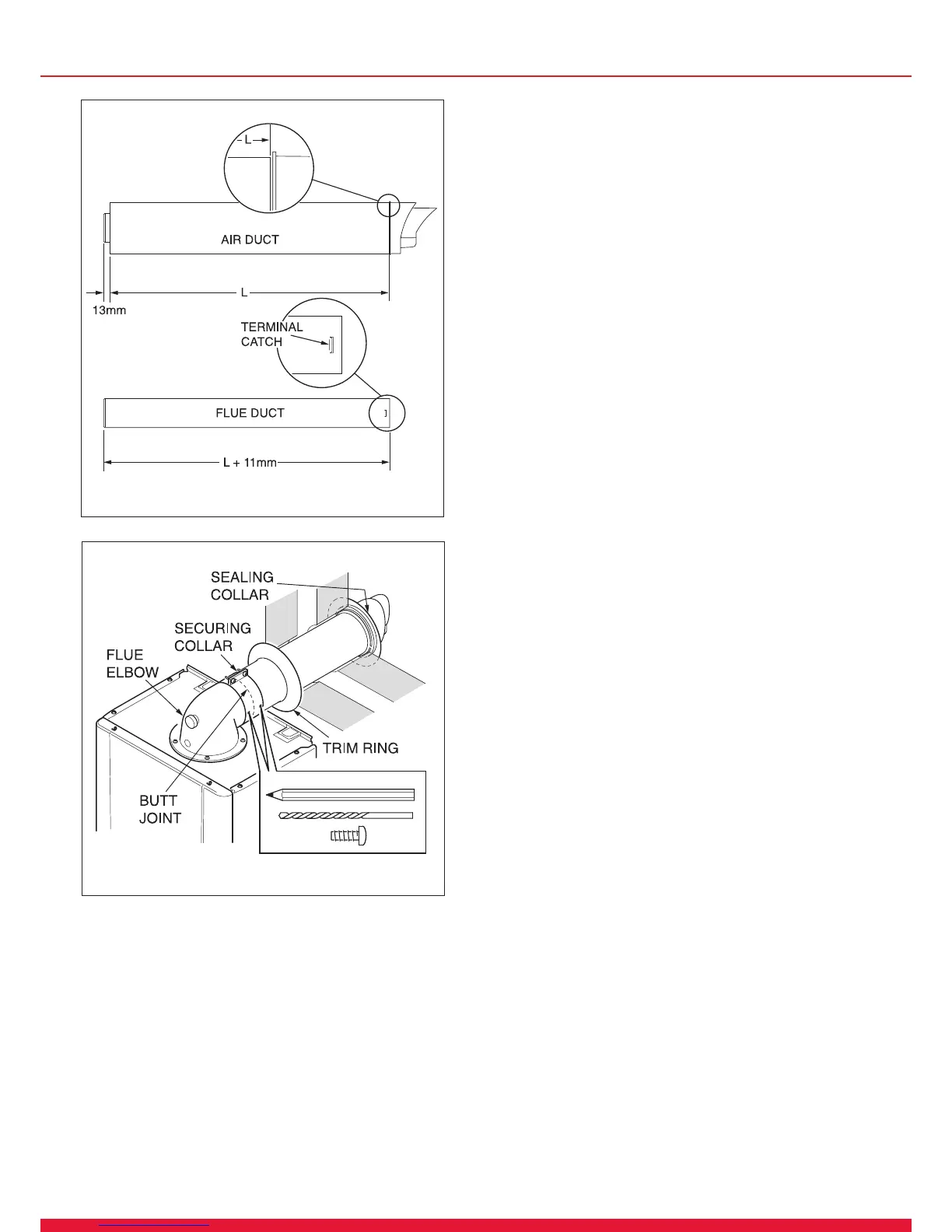
Separate the ue duct from the terminal by twisting to
release the terminal catch, then pull out of the retaining
seal, refer to diagram 10.17.
The ue duct cutting length (L + 11mm.) is shown in
diagram 10.17.
The air duct should be cut at the opposite end to the
terminal
The plastic ue duct MUST be cut at the opposite end to
the terminal catch.
The plastic ue duct extensions MUST be cut at the
opposite end to seal.
Insert the ue duct into the air duct terminal assembly,
remembering to engage the catch within the terminal.
Fit the sealing collar behind the locating lugs on the ue
terminal, see diagram 10.18.
Push the ue assembly into the wall, externally or internally,
initially until the end of the assembly protrudes a short
way from the inside face of the wall. This will enable the
internal trim ring (if required) to be positioned and allow the
ue assembly to be drawn back into the ue elbow.
Secure the ue elbow in position on top of the boiler with
four torque headed screws supplied.
Draw the ue assembly from wall and engage the ue duct
into the elbow and butt t between the air duct and ue
elbow.
Fit the securing collar into position.
Ensuring the correct alignment of the terminal, mark
through two of the pre drilled holes in the securing collar.
Remove securing collar and drill two 3mm diameter holes
one in the elbow and one in the air duct, take care not to
pierce the inner ue duct. Fit the securing collar and secure
with screws provided, see diagram 10.18.
Slide the internal trim ring back against the wall, securing in
place with a small amount of sealant if required.
NOTE: If the air and ue ducts have been correctly cut to
the instructions the sealing collar should t ush with the
outside wall.

 Loading...


