56
15 Replacement of Parts
15.10 Fan/Gas valve assembly
For access, refer to section 15.1.
Undo the tubing nut to remove the gas valve from the gas
pipe and any electrical connections, see diagram 13.6.
Remove the securing nut holding the fan retaining bracket,
press down on burner to ease removal of securing nut. Slide
out the fan retaining bracket.
Lift front of bracket away from stud and pull forward to release
the fan, see diagram 13.9.
Lift fan/gas valve assembly up and forward away from
locating studs.
Remove fan gasket and replace if necessary.
To replace the fan and retaining bracket correctly, insert into
slots on fan clamping bracket, see diagram 13.9, and locate
onto lugs on the burner.
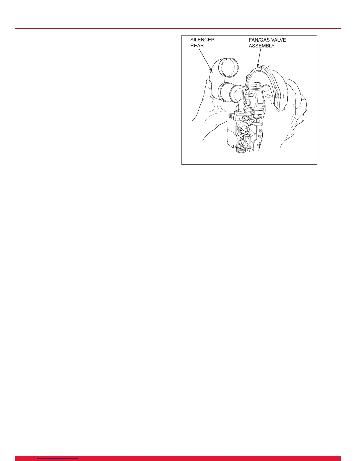
15.11 Silencer assembly (rear)
For access, refer to section 15.1.
Remove the fan/gas valve assembly, see relevant sections.
Pull Silencer rear away from fan/gas valve assembly.
The rear silencer is a push t so no tools or xings are
required for its removal or tting, see diagram 15.3.
15.12 Spark Electrode
For access, refer to section 15.1.
Remove the spark plug lead and earth lead.
Remove the two securing nuts, see diagram 13.5.
Withdraw the spark electrode by slowly pulling up and leaning
it forward towards the centre of the heat exchanger to ensure
that the electrode does not foul on the hole in the burner
casing.
Check spark gap.
15.13 Burner
For access, refer to section 15.1.
Remove igniter unit, ue hood, fan and gas valve assembly
and spark electrode lead, refer to relevant sections.
Remove the anged nuts and studs that secure the burner,
note that two studs at the rear also hold the fan clamping
bracket, see diagram 13.9.
NOTE: The burner gasket should be inspected but will not
need replacing unless there are signs of wear or damage.
IMPORTANT: Do not allow xings, nuts, screws, etc. to fall
into the open ue hood sump, use a temporary cover whilst
removing any parts.
Diagram 15.3
13007

 Loading...


