25
2000225228A
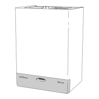
Diagram 10.3
PCB FUSE
PCB
SUPPORT
EXTENSION
PIECE
CONTROL
KNOB
12006
10 Replacement of Parts
Diagram 10.2
Diagram 10.1
THERMISTOR
P.C.B. CONNECTION
7168
SAFETY
TEMPERATURE
LIMITER
ELECTRICAL
CONNECTORS
UNION NUT
SECURING SCREW
If the safety temperature limiter operates at any other time, do
as above, the burner should relight. If the fault persists refer to
fault finding chart.
Note. Replacement of parts must only be carried out by a
competent person.
Before replacing any parts isolate the boiler from the electrical
supply and turn the gas supply off at the gas service cock, see
diagram 6.2.
Unless stated otherwise, all parts are replaced in the reverse
order to removal.
After replacing any parts always test for gas soundness and if
necessary carryout functional check of controls.
10.1 Access
Gain Access as Section 5.2.
10.2 Electrical Thermistor, Part No.227057
- diagram 10.1 and 10.2
Slacken control box securing screw , and swing out the control
box, see diagram 5.10.
Disconnect the thermistor plug from the control board by slightly
bending the retaining latch and removing the plug, see diagram
10.1.
Remove fan assembly, see section 5.3.
Unscrew the plastic R clips which retain all leads at the rear of
boiler.
Remove the retaining wire and withdraw the electrical thermistor
from its phial, see diagram 10.2.
Remove thermistor lead from the plastic R clips at rear of case
and the cable clips (these are located down left hand side of
boiler).
Draw thermistor lead followed by thermistor out through the
case grommet.
Re-assembly note. When fitting the thermistor make sure it is
fully inserted into the phial, see diagram 10.2. Take care when
re-threading as not to damage thermistor.
Refit the cable clips and the plastic R clips retaining the leads.
Refit the plastic retaining tag.
Refit the thermistor lead plug.
Refit fan assembly.
10.3 Safety Temperature Limiter,
Part No. 227038 - diagram 10.2
Gain Access as Section 5.2.
Remove air pressure switch, see diagram 10.6.
Remove the electrical connections from the Safety Temperature
Limiter, see diagram 10.2.
Undo retaining bracket screw and remove together with Safety
Temperature Limiter.
When refitting use the heat sink compound provided.
Re-assembly note. Check that Safety Temperature Limiter is
secure.
Note: Polarity of electrical connections is not important.
10.4 Control Board (PCB), Part No.
2000227135 - diagram 10.3
Remove casing, see Section 5.2.
RETAINING
BRACKET
THERMISTOR
PHIAL
RETAINING
WIRE
10272
PCB

 Loading...