0020094626_00 - 06/10 - Glow-worm
- 8 -
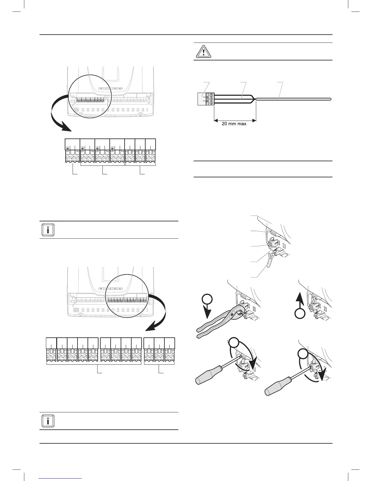
7.2 Internal connection
7.2.1 230V connectors
13
LN
230V~
13
LN
REL1
13
LN
REL2
13
LN
REL3
12
LN
REL4
12
LN
REL5
12
LN
IN1
321
Key
1 230 V connector (3-pin: earth / neutral / live)
2 Connectors (3 pins: earth / neutral / live):
REL1, REL2 and REL3
3 Connectors (2 pins: live / neutral):
REL4, REL5 and IN1
Consult the system manual for electrical connections
following installation.
The connector (1) is employed to connect the electricity supply.
7.2.2 24V connectors
12
21
OUT1
12
21
OUT2
12
21
OUT3
12
21
IN2
12
21
IN3
12
21
NTC1
12
21
NTC2
12
21
NTC3
12
21
NTC4
12
-+
EBUS
12
-+
EBUS
12
-+
EBUS
21
Key
1 Connectors (2 pins)
OUT1, OUT2, OUT3, IN2, IN3, NTC1, NTC2, NTC3 and NTC4
2 EBUS connectors (2 pins)
Consult the system manual for electrical connections
following installation.
Ensure correct polarity of ebus connections.
7.3 Electrical connections
1 32
Key
1 Connector
2 Electrical wires
3 Casing
e
Warning! When connecting electrical cables to a
connector in the control unit:
• Maintain a maximum distance of 20 mm between the
connector (1) and the outer insulation (3).
7.3.1 230V power supply
C
B
A
D
1
2
3
4
5
Key
1 230 V power cable
2 Break out tab
3 Anti-tamper connection
4 Power connection
5 Control unit
INSTALLATION
 Loading...
