0020094626_00 - 06/10 - Glow-worm
- 11 -
A room thermostat is assigned to an area in the building. If the
property has more than one zone, carry out the adjustments for
each zone.
The system may include 1 to 6 room thermostats and a wireless
outdoor temperature sensor.
9.5.1 Pairing with the Climapro
2
RF room
thermostat(s)
Adjustments must be made simultaneously to the control unit
and the room thermostat.
Via the control unit:
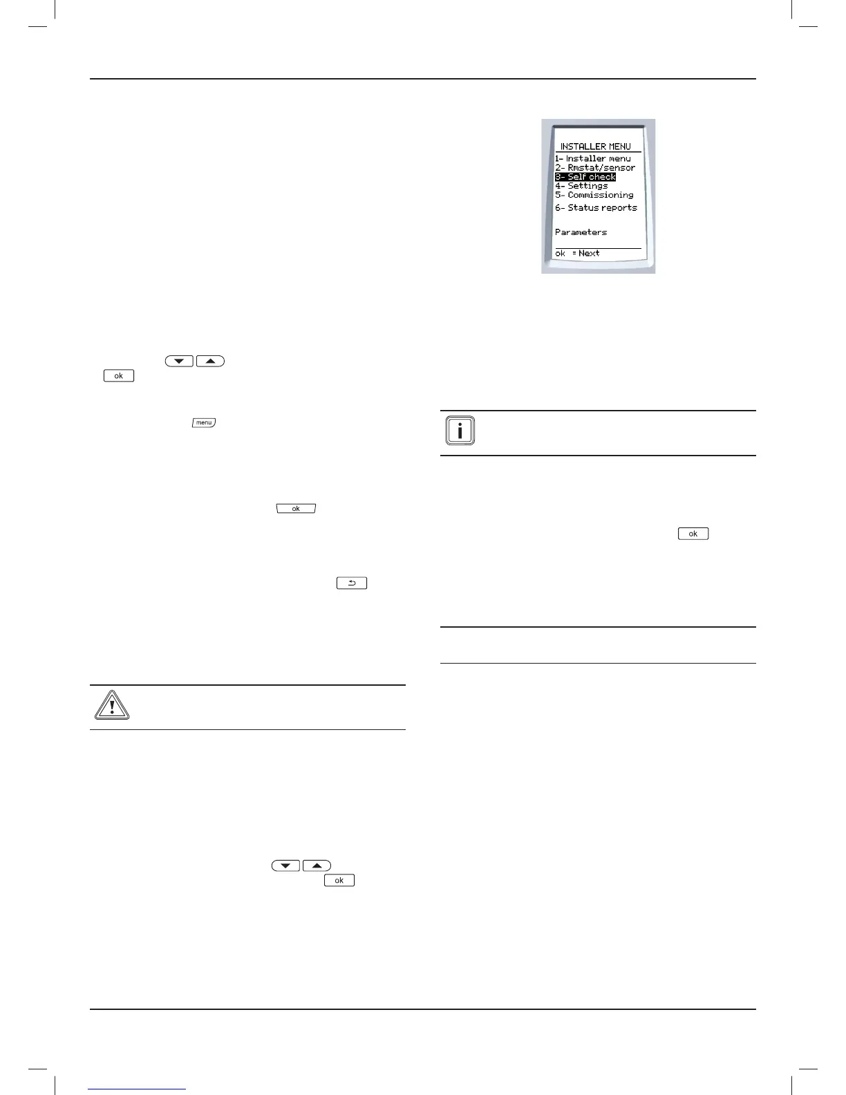
• From the installation menu in the control unit > select on the
screen > thermostat/sensor > room stat(s) press ok button
on the control unit.
• Select the area covered by the room thermostat by pressing
the buttons
.Confi rm by pressing the button
.
Via the room thermostat:
• Press the button
for 7 seconds.
• Enter the installer access code 96.
• Via the installer room thermostat menu > select on the
screen > RF > pairing
• Press the room thermostat button
.
The control unit and the room thermostat will immediately
indicate recognition on their respective "connection in progress"
screens.
If the message "Connection error" appears, press
and
repeat the operation.
9.5.2 Pairing with wireless outdoor sensor
• Consult the outdoor sensor’s installation manual in order to
carry out the operation.
The wireless outdoor sensor must be paired with
the Systempro control before installing the outdoor
sensor.
9.5.3 Outside temperature adjustment
This feature allows you to adjust the temperature measured by
the outdoor sensor (+ / - 5 ° C, with intervals of 1 ° C - factory
setting: 0).
• From the installation menu> select on the screen > 2-rmstat
/ sensor > outdoor sensor > external T ° correction
• Increase or decrease by pressing
) to display
the desired adjustment and press the button to
confi rm.
9.6 Automatic test
The automatic test allows you to check:
- EBUS inputs,
- NTC inputs,
- the RF connection with the Climapro
2
room thermostat,
- the outdoor sensor radio connection.
The other connections are not tested and should be
visually inspected during installation or confi guration
modifi cations.
• From the installation menu> select on the screen >
automatic test
• Switch on all the installation’s components.
• Confi rm the launching of the test by pressing
.
The result is displayed in seconds, indicating the status of each
appliance.
• If the status of a component is not correct, check the wiring
or relaunch the pairing.
e
Isolate the electrical supply to the equipment
prior to verifying or changing a connection.
• Carry out the necessary wiring work.
Once the power has been reconnected, the control unit returns
to the current control function.
• Repeat the test.
INSTALLATION
 Loading...
