0020094626_00 - 06/10 - Glow-worm
- 15 -
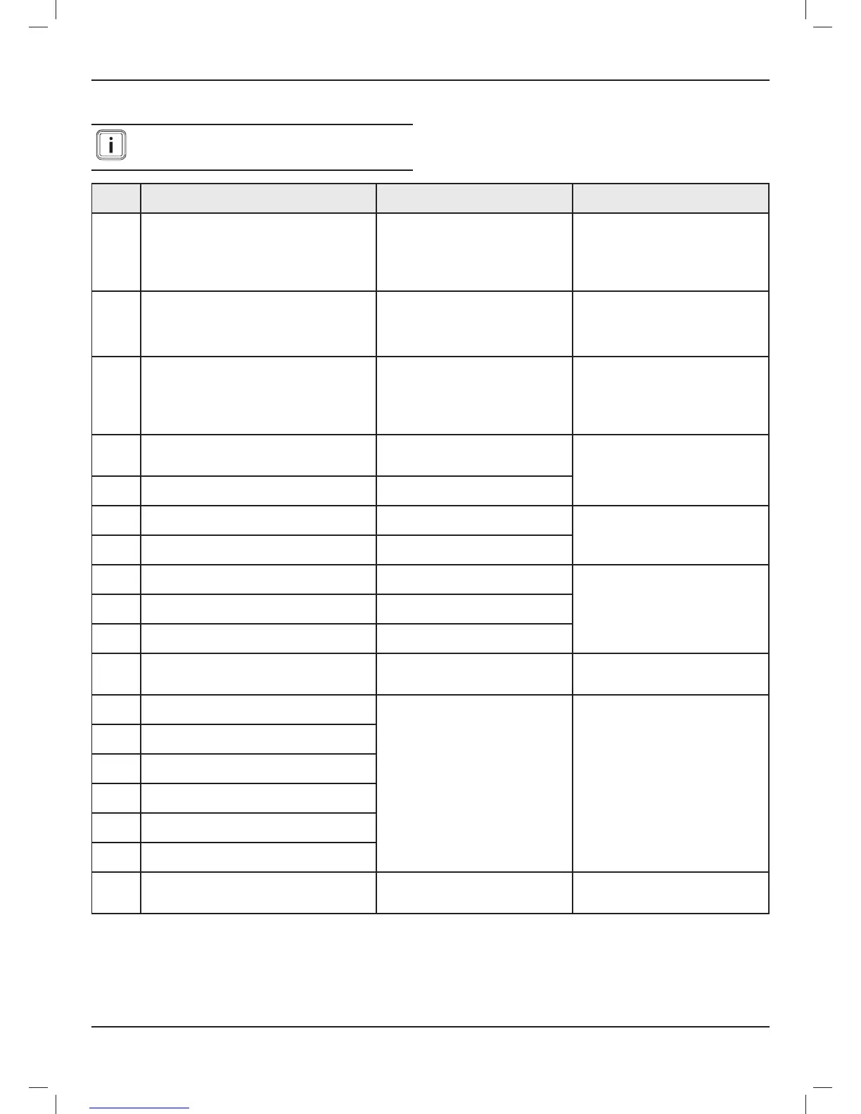
13.3 System failure codes
Faults described in this chapter should be carried
out by a qualifi ed engineer and if needed by the
After Sales Service.
Fault
codes
Description Cause Solution
001
Failure in Ebus communication between with the
boiler
The boiler is not connected to the control
unit.
The cable polarity is reversed.
The boiler is off.
Check that the boiler is connected to the
control unit.
Check the connection’s + / - polarity.
Ensure that there is no interruption to the
electricity network and that the boiler is
properly connected and turned on.
002
Failure in Ebus communication between with the
heat pump
The heat pump is not connected to the
control unit.
The heat pump is off.
Make sure the heat pump is connected to
the control unit.
Ensure that there is no interruption to the
electricity network and that the heat pump
is properly connected and turned on.
003
Failure in Ebus communication between with the
hydraulic module
The hydraulic module is not connected to
the control unit.
The hydraulic module is off.
Make sure that the hydraulic module is
connected to the control unit.
Ensure that there is no interruption to the
electricity network and that the hydraulic
module is properly connected and turned
on.
010
Heating circuit outgoing temperature sensor failure
(open circuit)
The sensor is defective or not
properly connected to the control unit
management or hydraulic module.
Check the sensor’s connections.
Verify that the position and the operation
of the sensor are correct.
Check the sensor’s resistance.
011
Heating circuit outgoing temperature sensor failure
(short circuit)
The sensor is shorted.
012
Heating circuit outgoing temperature sensor failure
low temperature (open circuit)
The sensor is defective or not properly
connected to the control unit.
Check the sensor’s connections.
Verify that the position and the operation
of the sensor are correct.
Check the sensor’s resistance.
013
Heating circuit outgoing temperature sensor failure
low temperature (short circuit)
The sensor is shorted.
014
Domestic water tank temperature sensor failure
(open circuit)
The sensor is defective or not properly
connected to the control unit.
Check the sensor’s connections.
Verify that the position and the operation
of the sensor are correct.
Check the sensor’s resistance.
015
Domestic water tank temperature sensor failure
(short circuit)
The sensor is shorted.
020 Pressure sensor failure
The sensor is defective or not properly
connected to the hydraulic module.
021 Pressure too low <0.5 bar
There is a leak in the heating circuit.The
degassing was not carried out correctly.
Check that there are no leaks.
Drain the heating circuit. Remove air.
Fill the installation.
030
Failure in communication with the zone 1 wireless
room thermostat.
The room thermostat is too far from the
control unit.
There is a problem with the batteries in
room thermostat.
Check the RF signal quality via the
Climapro RF installer menu.
Check the location of the thermostat.
Check that the thermostat’s batteries are
installed in their compartment.
Make sure the battery polarity is not
reversed.
Make sure the batteries are not dead.
If so, replace them with new batteries
031
Failure in communication with the zone 2 wireless
room thermostat.
032
Failure in communication with the zone 3 wireless
room thermostat.
033
Failure in communication with the zone 4 wireless
room thermostat.
034
Failure in communication with the zone 5 wireless
room thermostat.
035
Failure in communication with the zone 6 wireless
room thermostat.
036
Failure in communication with the wireless
outdoor sensor
The wireless outdoor sensor is too far
from the control unit.
Check the location of the outdoor sensor.
Check that the sensor’s power supply is
correctly provided by a photovoltaic cell.
MAINTENANCE
 Loading...
