0020094626_00 - 06/10 - Glow-worm
- 6 -
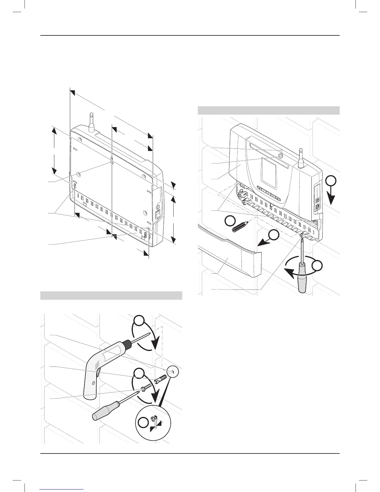
6.3 Installation
• Ensure that the materials used for installation are compatible
with those of the control unit.
• Determine the location of the installation. See the
"Placement selection" chapter.
290
145
126,5
128
23
1
3
2
145
143,5
Key
1 Control unit
2 Lower attachment holes
3 Upper attachment holes
Step 1
• Mark the upper wall attachment point.
A
B
C
5
1
2
3
Key
1 Upper screw
2 Plug
3 Holes
• Drill a Ø 6 mm hole (3) for the upper attachment point.
• Insert the plug (2) in the hole (3).
• Tighten the upper attachment point screw (1), leaving a
5 mm gap between the screw head and the wall.
Step 2
A
C
B
D
1
2
3
4
5
6
Key
1 Hatch screw
2 Control unit hatch
3 Lower attachment holes
4 Control unit
5 Upper screw
6 Upper attachment holes
• Position the control unit (4) by aligning the screw (5) and the
upper attachment hole (6).
• Slide the control unit (4) down.
• Unscrew the 2 screws securing the hatch (1)
• Remove the control unit hatch (2).
• Level the control unit (4).
• Mark the 2 lower wall attachment points (3), in line with the
mounting holes.
• Remove the control unit (4) by sliding along the wall.
INSTALLATION
 Loading...
