0020094626_00 - 06/10 - Glow-worm
- 9 -
• Gently remove the break out tab (2) from the control unit with
pliers (A).
• Connect the control unit following the order (B) to (D).
• Pass the power cable (1) through the anti-tamper connector
(3).
• Connect the power supply to the 230 V connector (4)
following the instructions given on the connector.
• Tighten the power cable (1) in the anti-tamper connector (3).
7.3.2 Other connections following the electrical
installation diagram
e
Warning! Risk of electric shock.
Break the grommets necessary for passing the
cables.
• Protect access to live parts, attach all cables to the control
unit with anti-tamper connectors.
Consult the system manual for electrical connections
following installation.
8 Commissioning
• Turn on the power supply to the control at the isolator.
1
2
Key
1 Control unit
2 Switch On (I) / Off (O)
• Turn on the control unit (1) with the switch (2) in position (I).
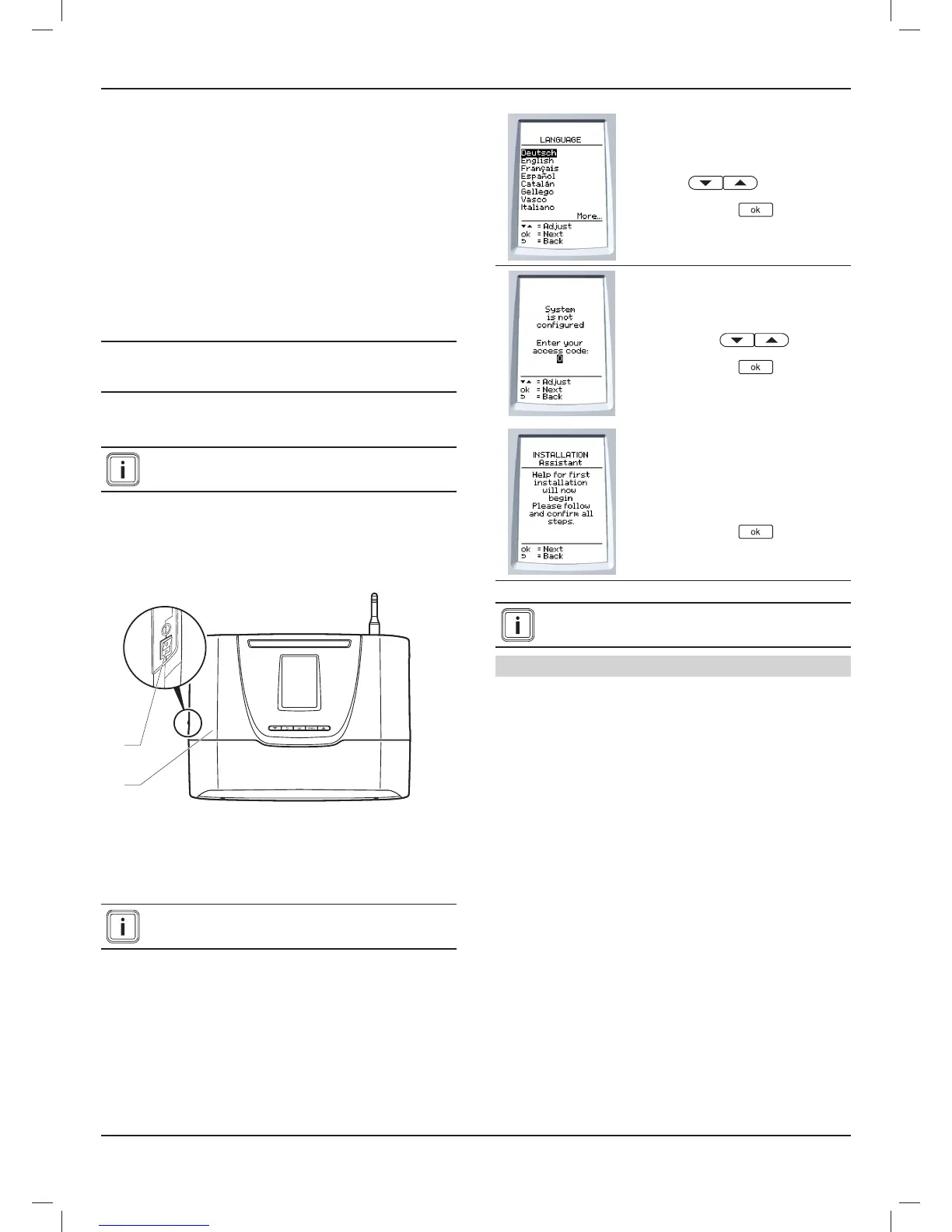
When connected for the fi rst time, the installation
menu is displayed.
• Choose the language with the
buttons .
• Press the button
to confi rm.
• Enter the installer access code 96
with the keys .
• Press the button
to confi rm.
• Follow and confi rm the steps
prompted by the initial installation
aid.
• Press the button
to confi rm.
Consult the system manual in order to install and
start-up the system.
Date and time
The date and time settings are confi gured via the Climapro
2
RF.
• Refer to the Climapro
2
RF instructions in order to adjust
settings.
INSTALLATION
 Loading...
