0020148679_00 - 11/12 - Glow-worm
- 12 -
INSTALLATION AND SERVICING
EN
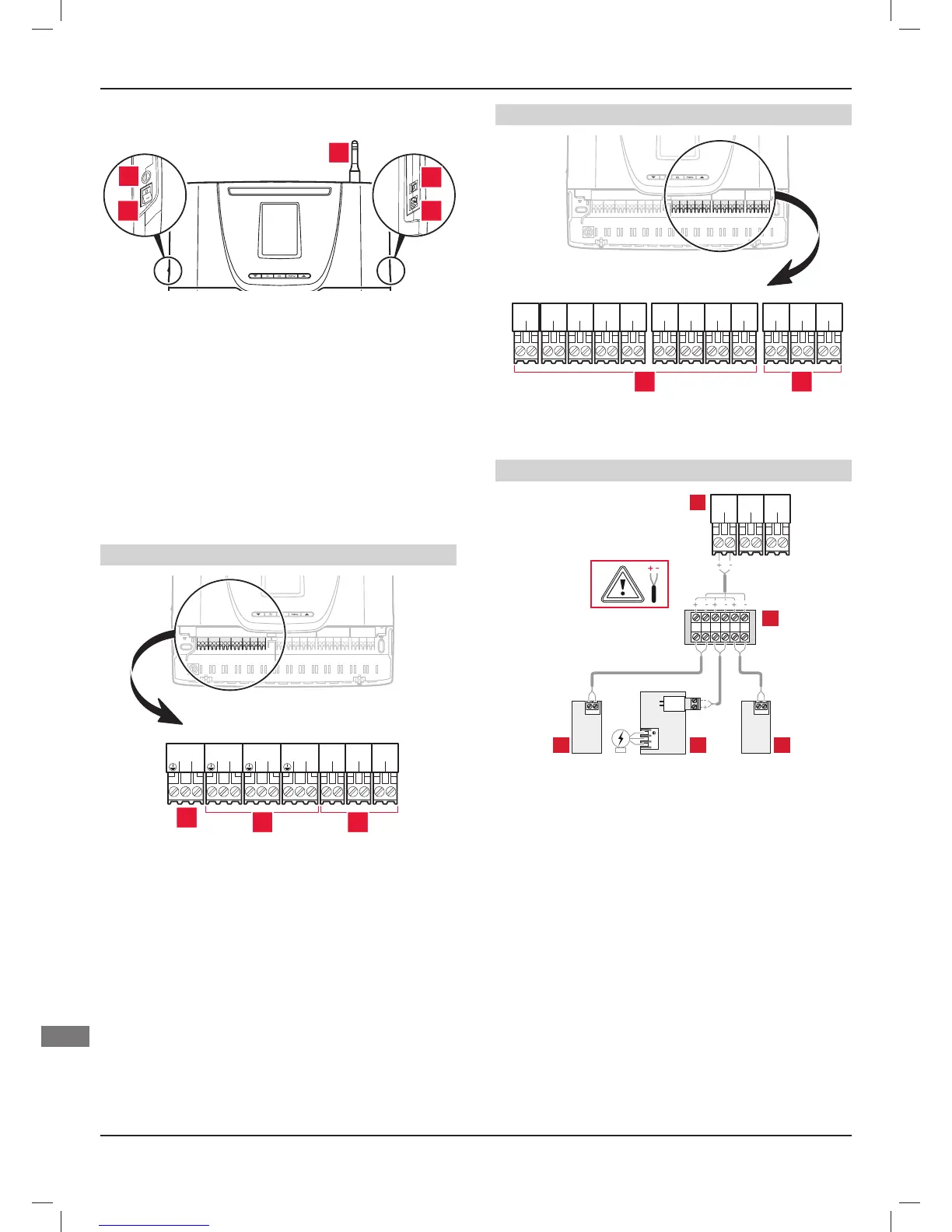
4.4.2 External connection
3
4
51
2
Key
1 Switch On (I) / Off (O)
2 Fuse 1AT 20mm
3 Antenna
4 RJ9 eBUS socket
5 RJ11 eBUS socket
The switch (1) is employed to cut the power supply before making
any changes to the electrical connection.
The electrical circuit of the equipment is protected internally by a
fuse (2).
The antenna is used for wireless connection with the
Climapro2 RF and the outdoor sensor.
4.4.3 Internal connection
230V connectors
13
LN
230V~
13
LN
REL1
13
LN
REL2
13
LN
REL3
12
LN
REL4
12
LN
REL5
12
LN
IN1
1
2 3
Key
1 230 V connector (3-pin: earth / neutral / live)
2 Connectors (3 pins: earth / neutral / live):
REL1, REL2 and REL3
3 Connectors (2 pins: live / neutral):
REL4, REL5 and IN1
The connector (1) is employed to connect the electricity supply.
24V connectors
12
21
OUT1
12
21
OUT2
12
21
OUT3
12
21
IN2
12
21
IN3
12
21
NTC1
12
21
NTC2
12
21
NTC3
12
21
NTC4
12
-+
EBUS
12
-+
EBUS
12
-+
EBUS
1 2
Key
1 Connectors (2 pins)
OUT1, OUT2, OUT3, IN2, IN3, NTC1, NTC2, NTC3 and NTC4
2 eBUS connectors (2 pins)
Example of multiple connections on an eBUS connector
BUSBUS
16A
NL
BUS
12
-+
EBUS
12
-+
EBUS
12
-+
EBUS
2
451
3
Key
1 wired outdoor sensor
2 eBUS Connectors (2 pins)
3 Connector block
4 Wired room thermostat
5 Boiler