0020148679_00 - 11/12 - Glow-worm
- 14 -
INSTALLATION AND SERVICING
EN
7.2 System failure codes
The fault status may be “inactive” (disappeared) "active" (still
aff ects the installation).
The installation can operate partially with a fault “active”. It is not
necessarily “blocking”. An alarm (not supplied) can be added to
the installation to signal certain faults. System failure codes are
described in the table of system failure codes (see chapter 10.2).
7.3 Control unit eBUS failures
Description Cause Solution
No display on
screen
The power
supply is faulty.
The fuse is
damaged.
Make sure that the electricity
supply has not been interrupted.
Check that 230V supply is turned on
and present.
Check the position of the control
unit switch.
Check the control unit’s fuse.
7.4 Resetting the control unit eBUS
This function allows you to reset the control unit (factory setting).
This restarts the installation assistant.
b
Caution.
• The resetting of factory settings is irreversible. Any
customised configuration of the control unit will be
lost.
∙ Simultaneously press the buttons
for 10 seconds.
∙ Confi rm by pressing
ok .
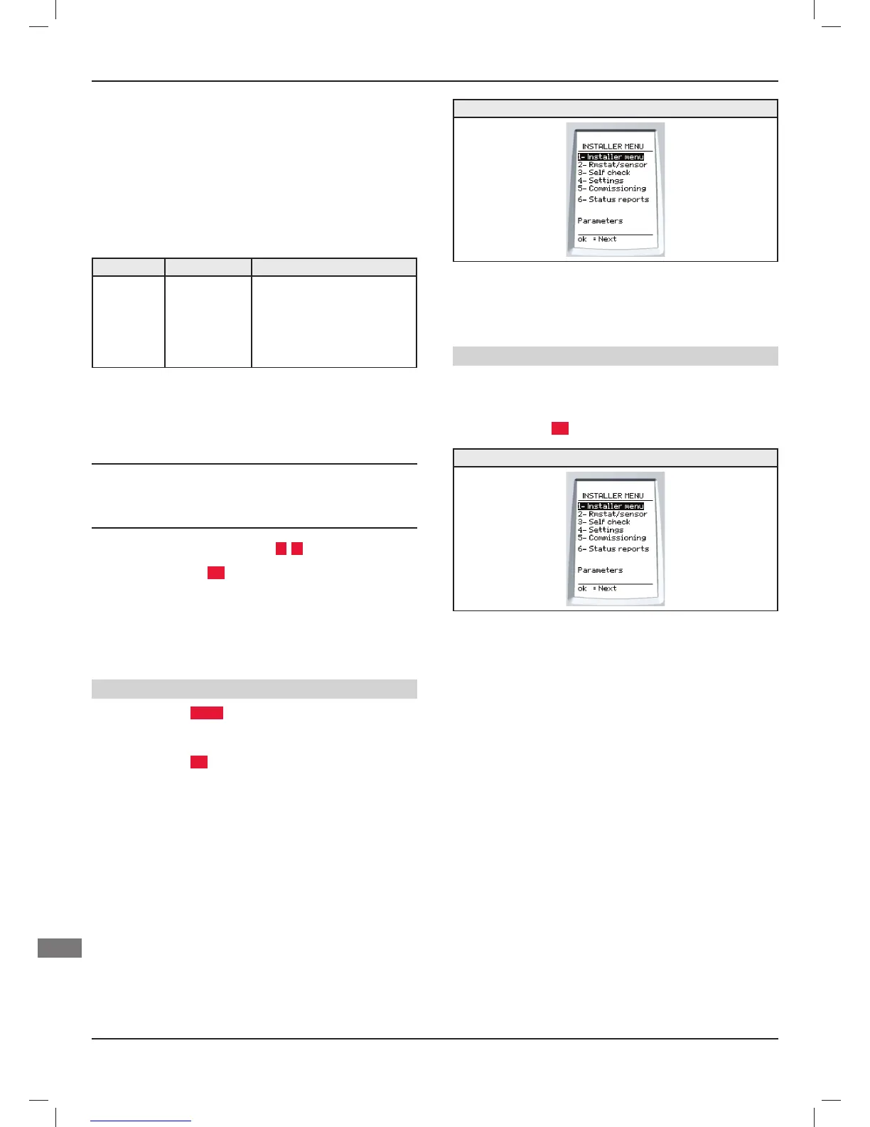
7.5 Installation menu
The installation menu is still accessible after commissioning.
Menus and functions are described in the table of menus and
functions (see chapter 10.1).
Access to the installation menu
∙ Press the button
menu for 7 seconds.
∙ Enter the installer access code 96.
∙ Press the button
ok to confi rm.
Individual installation
- Check the proper operation of external control items (room
thermostat, outside sensor...).
7.6 Maintenance menu
Access to the maintenance menu
∙ Press the “menu” button for 7 seconds.
∙ Enter the installer maintenance access code 35.
∙ Press the button
ok to confi rm.
Individual installation
The maintenance menu includes the installation menu function,
plus 2 additional functions:
- "System tests", within the maintenance menu,
- "After sales service Info", in the options.
7.6.1 System tests
This menu allows you to test the operation of all the appliances
and the system (boiler, HP, valve,) present in the installation.
Each element can be controlled centrally by activating its normal
start-up function or by individual component.
By entering the test menu, the control unit displays the following
message: “the system is currently stopped" No further heating
control operations are aff ected. Control is resumed upon exiting
the menus.