0020148679_00 - 11/12 - Glow-worm
- 9 -
INSTALLATION AND SERVICING
EN
4 Mounting and installation
i
All the dimensions shown of the illustrations are
expressed in millimetres (mm).
4.1 Check scope of delivery
∙ Please check the scope of delivery for completeness.
- Control unit eBUS
- 2 bags of screws and plugs
- 2 sachets of 7 strain relief connectors (one strain relief
connector in place)
4.2 Control unit location
Install the system:
- in a room protected from frost,
- at 1.50 metres from the ground (according to current
regulations) to ensure a accessibility for reading.
- near to the appliances, in compliance with the appliances
accessibility and safety requirements.
Do not install the control unit:
- close to heat sources such as radiators, chimney walls,
televisions, sun rays,
- above a cooking device capable of generating steam and
grease,
- in a room with a lot of dust or with a corrosive atmosphere.
1500
290
264
45
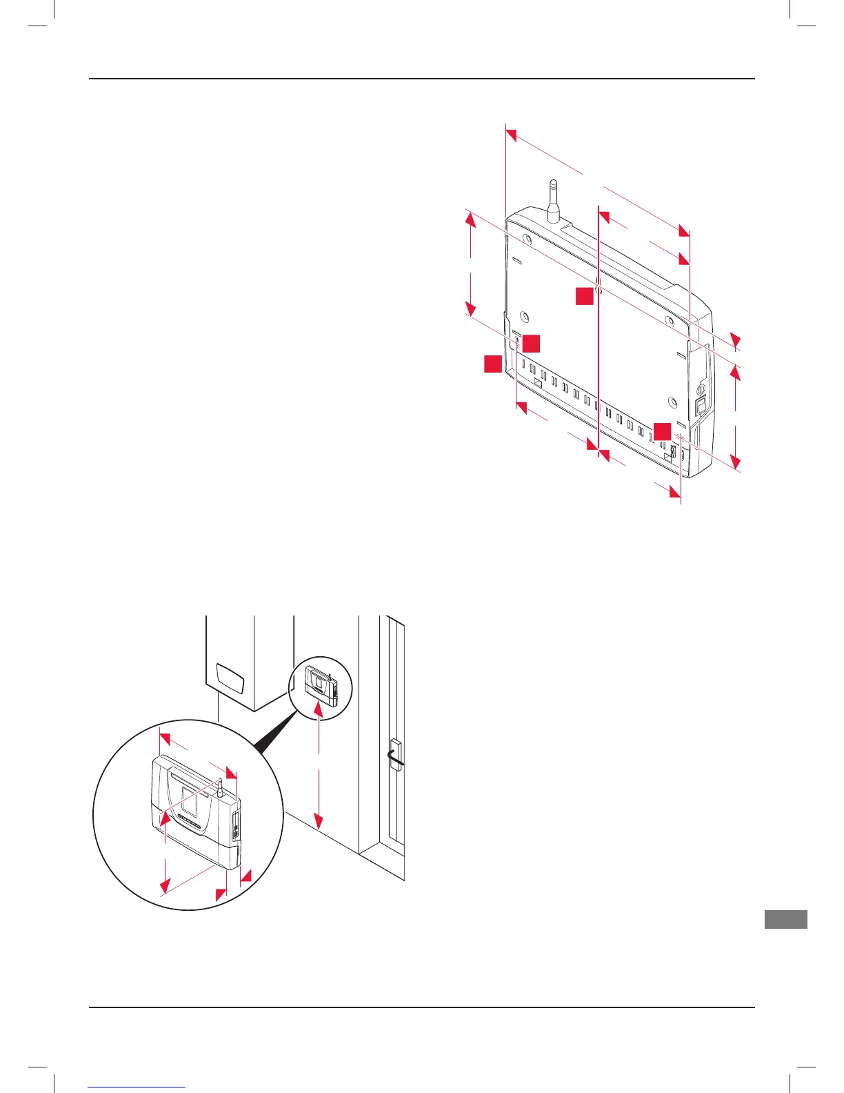
4.3 Wall-mounting of the product
290
145
126,5
128
23
145
143,5
3
2
2
1
Key
1 Control unit
2 Lower attachment holes
3 Upper attachment holes