37
11 Commissioning
11.1 Preliminaries - All Systems
The commissioning should be carried out by a competent
person in accordance with the current issue of BS6798.
DO NOT operate the boiler without water.
Make sure that the system has been thoroughly flushed
out with cold water and that all cleanser, if used, has been
removed.
Isolate the boiler from the mains electrical supply.
Test for gas tightness and purge air from the gas supply.
11.2 LPG Conversion
All models can be converted to run on LPG-Propane (G31).
This conversion should be carried out by a competent
person as described in section 11.11.
11.3 Filling the Heating Circuit
With the gas isolation valve closed and with no demand from
any external controls.
1. Fill the heating system.
Sealed system only - fill the system to a pressure of
1.0bar.
2. Vent all air from the system - repeat as neccessary
until the system is full and all the air has been vented.
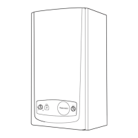
11.4 Initial Lighting
NOTE: If you have fitted a Glow-worm Options Board Kit,
please refer to the instructions supplied with the kit for
completion of commissioning.
Do not operate the boiler without water.
Refer to diagram 11.1
1. With no demand from any external controls, switch on the
electrical supply to the boiler.
Open the gas service isolation valve, see diagram 11.2.
2. Select your required function by pressing “ Mode “, scroll
through your options and select one of the following:-
Central heating.
Boiler functions ALL swicthed off.
“OFF”
3. Turn ON your external controls and select the room
temperature required.
The boiler will operate automatically.
NOTE: The display will indicate the Heating system water
temperature or a fault code if in a fault condition.
11.5 Gas Inlet Pressure
Check the supply pressure at the gas service isolation valve
test point, see diagram 8.1.
The nominal supply pressure should be 20mbar when the
appliance is operating at the maximum heat input. This can
be achieved by turning on several hot water taps.
NOTE: There is a pressure drop over the gas service isolation
valve prior to the inlet pressure test point, this is normal and
the inlet pressure to the main gas valve can be up to 2mbar
less than the supply pressure to the boiler at the maximum
heat input. Additionally the safe nominal maximum heat input
of the appliance can be achieved at an inlet pressure down to
15mbar.
Diagram 11.1
13473

 Loading...