Supplied By www.heating spares.co Tel. 0161 620 6677
37
12 Commissioning
13577
12.1 Preliminaries - All Systems
The commissioning should be carried out by a competent
person in accordance with the current issue of BS6798.
Do Not operate the boiler without water.
Make sure that the system has been thoroughly flushed
out with cold water and that all cleasnser if used has been
r
emoved.
Isolate the boiler from the mains electrical supply and test for
gas soundness and purge air from the gas supply.
12.2 LPG Conversion
All models can be converted to run on LPG-Propane (G31).
This conversion should be carried out by a competent
person as described in section 12.11.
12.3 Filling the Heating Circuit
With the gas service isolation valve closed and with no
demand from any external controls switch on the power
supply to the boiler.
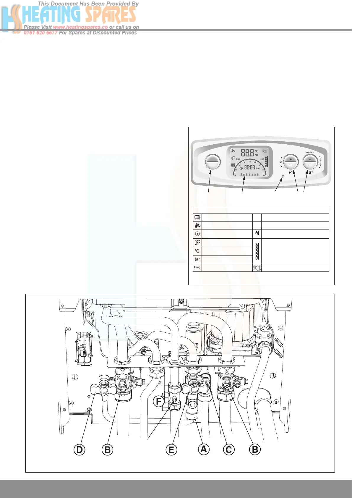
The boiler should be in “OFF” mode, this will be indicated
on the user interface display, refer to diagram 12.1. If not,
press the “Mode” button repeatedly until the “OFF” symbol is
displayed, then continue as follows:
1. Connect the flexible hose to the double check valve and
secure by tightening the knurled nut marked ‘A’, refer
diagram 12.2.
2. Open the Central Heating Flow and Return isolation
valves marked ‘B’ using a screwdriver or a 4mm allen key
- slot in line with the axis of the isolation valve (shown
closed in diagram).
3. Ensure ALL cold water taps are shut off then open
the Domestic Cold Water isolation valve marked ‘C’ using
a screwdriver or a 3mm allen key - slot in line with the
axis of the isolation valve (shown closed in diagram).
4. Open the tap ‘D’, then gradually open tap ‘E’ through 90
o
to fill the heating system to a pressure of 1.0bar then
close the two filling taps.
5. Vent all air from the system - repeat step 4 as neccessary
until the system is full and all the air has been vented.
6. To comply with the water regulations the flexible hose
must be disconnected fr
om the double check valve close
the taps ‘E’ and ‘D’ then undo the knurled nut marked ‘A’
and pull the flexible hose fr
om the double check valve.
Diagram 12.1
13176
MODE
PROG
SYMBOLS DISPLAYED ON THE LCD AND DESCRIPTIONS
Will be displayed when domestic hot
water temperature is less than 50
o
C
System Pressure
Max burner display
Glow-worm control (Optional)
Outdoor sensor (if fitted)
Min burner display
Temperature
Appliance OFF
Central Heating
Timed Mode
Programmer
Adjustment Mode
Domestic Hot Water Function
Central Heating Function
Ext
Eco
LCD
DISPLAY
RESET
BUTTON
DHW CH
TEMPERATURE
ADJUSTMENT
TOGGLE BUTTON
MODE and PROG
Diagram 12.2
GAS SERVICE
ISOLATION VALVE
PRESSURE
TEST POINT
 Loading...


